Product Transition Guide
G+ Mini Rev:
G+ Mini Transition Guide September 2008
Page 8 of 24
Magnetek, Inc.
Note: The current input for terminal A1 is not available on the G+ Mini. Use terminal A2 for current input.
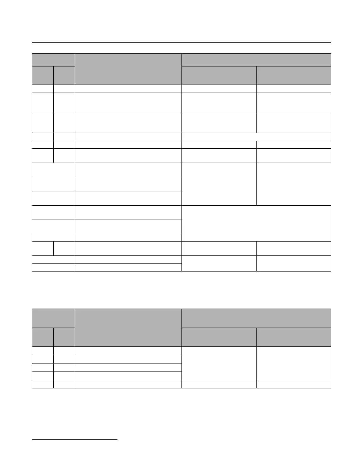
Network Communications Terminals
• "–" indicates that an equivalent terminal on the other unit does not exist.
FS +V Analog input power supply +12 V (max. current 20 mA) +10.5 V (max. current 20 mA)
FR A1
Analog input 1
Voltage or current (not available on G+ Mini -
see Note) input (frequency reference)
0~+10 VDC (20 kW),
0 or 4~20 mA (250 kW)
0~+10 VDC (20 kW)
—A2
Analog input 2
(frequency reference)
—
DC:0~+10 V (20 kΩ)
0 or 4~20 mA (250 kΩ)
(initial setting: 4-20 mA)
FC AC Analog input common 0 V
— HC Hard wire baseblock common — +24 V (max. current 10 mA)
—H1
Hard wire baseblock input
(EN954-1, category 3, Stop category 0)
—
Open: Stop
Closed: Operation
MA
Multi-Function Digital Output
(N.O. Contact) (Fault)
Max. AC load:
250 VDC, 1 A max.
30 VDC, 1 A max.
Max. load:
AC:250 V, 10 mA~1 A
DC:30 V, 10 mA~1 A
MB
Multi-Function Digital Output
(N.O. Contact) (Fault)
MC
Multi-Function Digital Output
(common)
P1
Open collector output 1
(during run)
Photocoupler +48 VDC, 50 mA or less Output
P2
Open collector output 2
(speed agree)
PC Open collector output common
—MP
Pulse output
(output frequency)
— Max. 32 kHz
AM Analog output
DC:0~+10 V, 2 mA max.
Resolution: 8 bit
DC:0~+10 V, 2 mA max.
Resolution: 1/1000
AC Analog output GND
Serial
Communication
Terminals
Function
Signal Level
P3
Series
2
G+
Mini
P3 Series 2 G+ Mini
R+ R+ Receive +
RS-485/422 MEMOBUS
Protocol
Max. 19.2 kbps
RS-485/422 MEMOBUS
Protocol
Max. 115.2 kbps
R- R- Receive -
S+ S+ Transmit +
S- S- Transmit -
GND IG Shield connection, GND 0V 0V
Control
Terminals
Function
Signal Level
P3
Series
2
G+
Mini
P3 Series 2 G+ Mini
 Loading...