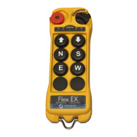
Flex Duo™
Radio Control Equipment
Quick Reference Manual
NOTE: The full Flex Duo Instruction Manual can be found at www.columbusmckinnon.com/magnetek.
Consult the Instruction Manual for any desired feature not included in this quick reference manual.
191-32000-M001 R00
September 2020
© Copyright 2020 Magnetek
N49 W13650 Campbell Drive
Menomonee Falls, WI 53051
Distributed by Tri-State Equipment Company Inc.
sales@tsoverheadcrane.com
www.tsoverheadcrane.com
Tel: (314) 869-7200
Flex Duo Quick Reference Manual
191-32000-M001 R00
September 2020 © Copyright 2020 Magnetek
MRX Wiring Diagram
x In the single speed model, relay K1 is for PB1 and relay K2 is for PB2.
x Relay K3 is not used in the single speed model.
x In the dual speed model, relay K1 is first speed for PB1, relay K2 is first speed for PB2, and relay K3 is shared
as a second speed for PB1 and PB2.
Relay
PB1
2
ND
Speed
PB1
1
ST
Speed OFF
PB2
1
ST
Speed
PB2
2
ND
Speed
K1 X X
K2 X X
K3 X X
x MAIN Relays K27A(NC), K27A and K27
B change state when the system is turned on and remain latched while
the system is turned on. When the system is turned off, these relays revert to their normal state.
x FUNC Relay K10 is an auxiliary relay that closes during the START / ON sequence and opens when PB1 and
PB2 are released.
x For 9-36VDC power supply, wire #1 corresponds to the negative charge (-), wire #3 corresponds to the positive
charge (+), and wire #2 is for GROUND.
x The circled numbers in the output diagrams above correspond to the wire numbers in the harness.
x Suppressors are recommended on contactors being driven by Flex relays due to the possibility of voltage
spikes.