
L
lauren16Aug 7, 2025
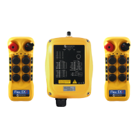
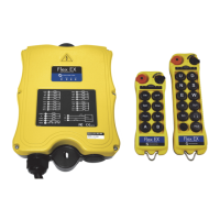
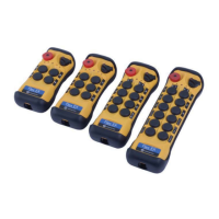
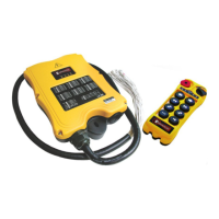
What to do if Magnetek Enrange Flex EX Remote Control outputs don't match the transmitter?
- MMarcus JohnstonAug 7, 2025
If the outputs of your Magnetek Remote Control do not correspond to the transmitter, check the system wiring again.