EasyManua.ls Logo

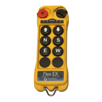
Magnetek FLEX-6EX User Manual

Magnetek FLEX-6EX
39 pages
To Next Page IconTo Next Page
Page #1 background imageLoading...
Page #1 background image
Flex 6EX System
Radio Control Equipment
Instruction Manual
0-FLEX-6EX-ME R3
March 2016
© Copyright 2016 Magnetek Material Handling

Table of Contents

Questions and Answers:

Magnetek FLEX-6EX Specifications

Frequency Specifications IconFrequency Specifications
frequency range433 - 434 MHz
frequency deviation12.5 KHz
number of channels62 channels
Transmission Specifications IconTransmission Specifications
transmitting range>100 Meters / 300 Feet
transmitting power0.3mW
modulationDigital Frequency Modulation based on Manchester Code, 20bit address, 32bit CRC Parity Check and Hamming Code
Receiver Specifications IconReceiver Specifications
receiver typeFrequency Auto Scanning
receiver sensitivity-116dBm
receiver power consumption11.0 VA
Power and Voltage IconPower and Voltage
output contact rating250V @ 8 Amps
transmitter operating voltageDC 3.0V
receiver supply voltageVoltage Setting Min ~ Max 24VAC (22 ~ 26VAC) 42VAC (38 ~ 46VAC) 48VAC (43 ~ 53VAC) 110VAC (104 ~ 126VAC) 220VAC (207 ~ 253VAC) 380VAC (351 ~ 429VAC) 410VAC (400 ~ 480VAC) 12/24VDC (9 ~ 36VDC)
Operating Environment IconOperating Environment
operating temperature-25°C -- 75°C / -13°F -- 167°F
antenna impedance50 ohms
enclosure ratingIP-66
Dimensions and Weight IconDimensions and Weight
transmitter dimension184mm (L) x 69mm (W) x 34mm (H)
receiver dimension165mm (L) x 125mm (W) x 75mm (H)
transmitter weight242g / 8.5oz
receiver weight1.8kg / 4.0 lb (include output cable)

Summary

Introduction

Radio Controlled Safety

Warnings and Cautions

Highlights critical items for personnel and equipment protection, defining WARNING and CAUTION statements.

Critical Installation Considerations

Essential safety precautions prior to installation and operation of the equipment.

General Safety Guidelines

General safety advice for operating radio-controlled equipment in proximity to people.

Authorized Operators

Defines who is permitted to operate radio-controlled cranes and equipment.

Operator Safety Information and Training

Knowledge and skills required for safe operation of radio-controlled equipment.

Transmitter Unit

Guidelines for the proper use and storage of the transmitter unit.

Pre-Operation Test

Mandatory checks to perform before operating the equipment at the start of a shift.

Handling Batteries

Safety procedures for handling, charging, and disposing of batteries.

Optional Rechargeable Battery Handling

Specific instructions for handling rechargeable batteries and chargers.

Battery Disposal

Consult local regulations for proper battery disposal procedures.

Crane/Lifting Device Specific Warnings

Critical safety warnings related to cranes, hoists, and lifting devices.

Specific System Warnings

Operating safety tips specific to the Flex 6EX System.

General Systems Information

Transmitter Handset

Overview of the transmitter handset components and features.

Transmitter Handset External Illustration

Diagram showing the external components of the transmitter handset.

Transmitter Handset Internal Illustration

Diagram showing the internal components of the transmitter handset.

Receiver Unit

Overview of the receiver unit components and features.

Receiver Unit External Illustration

Diagram showing the external components of the receiver unit.

Receiver Unit Internal Illustration

Diagram showing the internal components of the receiver unit.

Function Settings

Transmitter Handset Settings

Configuration options for the transmitter handset.

System Channel Settings

Procedure for setting the system channel on the transmitter.

Channel Change via Push Buttons

Method for changing the transmitter channel using push buttons.

Optional 4-Digit Security Code

Instructions for programming and using the optional 4-digit security code.

I-CHIP Functionality

Explanation of the I-CHIP's role in storing and transferring system information.

Receiver Unit Settings

Configuration options for the receiver unit.

Receiver System Channel Settings

Procedure for setting the system channel on the receiver unit.

Output Relay Configurations

Details on output relay configurations and types.

Output Relay Types

Description of 3-relay and 4-relay output configurations.

Output Relay Actions at 2nd Speed

How output relays function at the second speed setting.

START/AUX Function

Functionality of the START position as an auxiliary function.

Momentary Contact

Explanation of momentary contact type for output relays.

Toggled Contact

Explanation of toggled (latching) contact type for output relays.

Auxiliary STOP Push Button Function

Functionality of the auxiliary STOP push button.

Receiver Auto-Scanning Settings

Configuration options for the receiver's auto-scanning feature.

Dip-Switch Settings

Configuration using dip-switches on the receiver module.

Interlocked Functions

Description of interlocked settings for adjacent push buttons.

Non-Interlocked Functions

Description of non-interlocked settings for simultaneous push button use.

Jumper Settings

Configuration options using jumpers on the decoder/relay board.

I-CHIP Programming Port

Location and use of the I-CHIP programming port.

Fuse Ratings

Table detailing the fuse types and ratings for different voltage inputs.

System Channels Table

Receiver Installation

Output Relay Contact Diagram

Diagram illustrating the output relay contact connections.

Pre-Installation Precautions

Essential checks and precautions before installing the receiver unit.

Step-by-Step Installation

Detailed instructions for installing the receiver unit.

System Testing

Operating Procedure

Transmitter Operation

Procedures for operating the transmitter unit.

General Operating Procedure

Step-by-step guide for the general operation of the transmitter.

Automatic Channel Scanning Operating Procedure

Procedure for automatic channel scanning and receiver lock-on.

Changing Transmitter Batteries

Instructions for replacing the transmitter batteries.

Status Light Indicators and Warnings

Explanation of status light indications on the transmitter and receiver.

Transmitter Status Light Indication

Details on the meaning of different status light indications on the transmitter.

Receiver Status Light Indication

Details on the meaning of different status light indications on the receiver.

Receiver SQ Light Indication

Explanation of the receiver's SQ (Signal Quality) light indication.

Receiver Power Light Indication

Explanation of the receiver's POWER light indication.

Receiver COM Light Indication

Explanation of the receiver's COM (Communication) light indication.

Trouble Shooting Tips

Common problems and their suggested solutions for the system.

System Specifications

Related product manuals