Do you have a question about the Magnetek Flex Duo and is the answer not in the manual?
Defines safety message conventions used throughout the manual.
Highlights essential safety warnings and requirements for equipment installation.
Provides general operational guidelines for radio-controlled equipment.
Specifies criteria for personnel authorized to operate radio-controlled equipment.
Outlines essential knowledge, skills, and prohibited actions for operators.
Details proper handling and storage procedures for the transmitter unit.
Describes essential pre-operation tests for safety and functionality.
Provides critical warnings and guidelines for battery handling and charging.
Explains the procedure for replacing transmitter batteries.
Details operation, charging, and mounting for the optional battery charger and its components.
Describes the step-by-step procedure for operating the Flex Duo system.
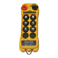
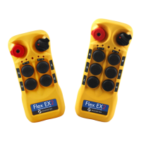
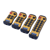
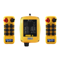
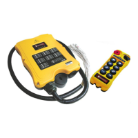
Details the transmitter unit's external illustration and components.
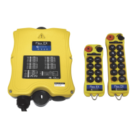
Details the receiver unit's external illustration and components.
Illustrates output relay contact diagrams for single-speed and dual-speed models.
Details the meaning of various status light displays on the transmitter.
Details the meaning of various status light displays on the receiver.
Explains the receiver power status light indications.
Explains the receiver COM status light indications.
| Operating Frequency | 433.92 MHz |
|---|---|
| Operating Voltage | 3.0 V DC |
| Battery Type | AA Alkaline |
| Frequency | 433.92 MHz |
| Operating Range | 100m (open area) |