Flex Duo Operator Manual
August 2021
Page 17
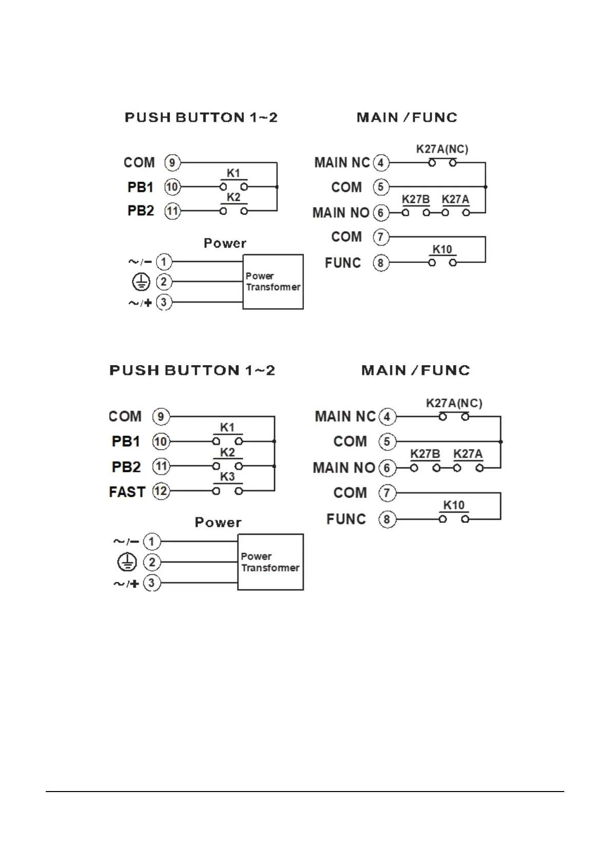
3.3.2 Output Relay Contact Diagrams
Figure 3-4
• The default operation of the Flex Duo system will have the two pushbuttons configured as a pair to perform as
an interlocked motion control with the corresponding output relays set up for momentary contact closure.
• For 9-36VDC power supply, wire #1 corresponds to the negative charge (-), wire #3 corresponds to the positive
charge (+), and wire #2 is for GROUND.
• The circled numbers in the output diagrams above correspond to the wire numbers in the harness.
• Suppressors are recommended on contactor, capacitive loads or inductive loads being driven by Flex relays
due to the possibility of voltage spikes.