Flex 6EX System Instruction Manual
March 2016
Page 28 of 38
6. RECEVIER INSTALLATION
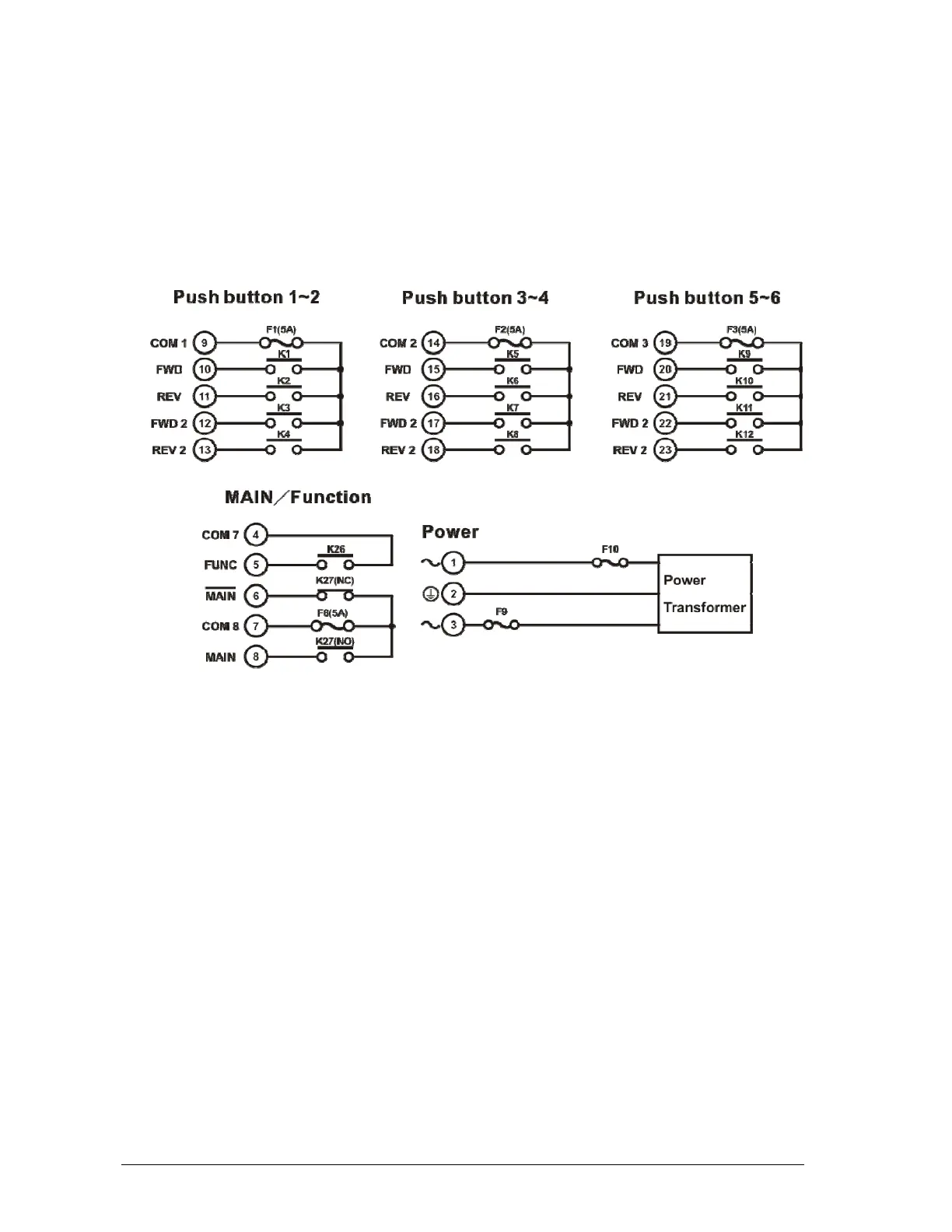
6.1 OUTPUT RELAY CONTACT DIAGRAM
* For 3-relay (shared 2
nd
speed) and 4-relay (separate 2
nd
speed) configurations please refer to page 20.
* For 4-relay closed/closed and 4-relay opened/closed relay configurations please refer to page 20.
* For 12-24VDC power supply, wire #1 corresponds to the negative charge (-) and wire #3 corresponds
to the positive charge (+). Wire #2 is for GROUND.
* Wire #6 is for “Normal Close” and wire #8 is for “Normal Open” MAIN output.