Flex 6EX System Instruction Manual
March 2016
Page 26 of 38
SYSTEM FUN CTIO NS
TEST
JP7
JP6
JP5
JP4
JP3
JP2
JP1
I-CHIP PORT
I-CHIP PORT
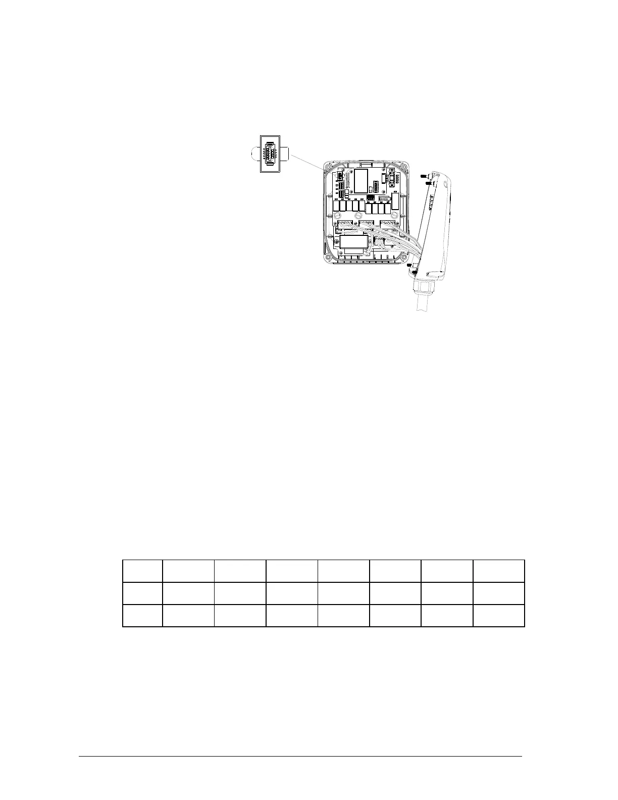
4.2.6 I-CHIP Programming Port
(Fig. 15)
The I-CHIP programming port, located on the decoder module (refer to Fig. 15 above) inside the
receiver, is designed for the purpose of transferring a system serial number/ID code from the I-CHIP
to the receiver or vice versa. If you wish to transfer system information from the receiver to the I-
CHIP, just insert the I-CHIP onto the programming port (JP6 jumper not inserted), wait until the
Status LED on the decoder module displays a constant green light (within 2 seconds), and then take
the I-CHIP out of the programming port (programming completed). At this time the I-CHIP should
also possess the same serial number/ID code as the receiver.
If the Status LED on the decoder module displays a constant red light after inserting the I-CHIP
(programming failed), then you must reinsert the I-CHIP one more time. On the other hand, if you
wish to transfer system information from I-CHIP to receiver, then you must first insert JP6 jumper
prior to inserting the I-CHIP, then wait for the green light to appear on the Status LED. At this time the
receiver should also possess the same system information as the I-CHIP. Please note that the
receiver unit must be powered in order to proceed with the programming.
4.2.7 Fuse Ratings
FUSE # 110 -
120VAC
220 -
240VAC
380 -
400VAC
410 -
460VAC
24VAC 42 & 48VAC 12 - 24VDC
F1 - F8 5.0A (clear) 5.0A (clear) 5.0A (clear) 5.0A (clear) 5.0A (clear) 5.0A (clear) 5.0A (clear)
F9 - F10 0.5A (blue) 0.5A (blue) 0.5A (blue) 0.5A (blue) 1.0A (red) 1.0A (red) 2.0A (red)