Flex 8EX EU System Instruction Manual
March 2012
24 of 37
JP7
JP1
JP5
JP3
JP2
JP4
JP6
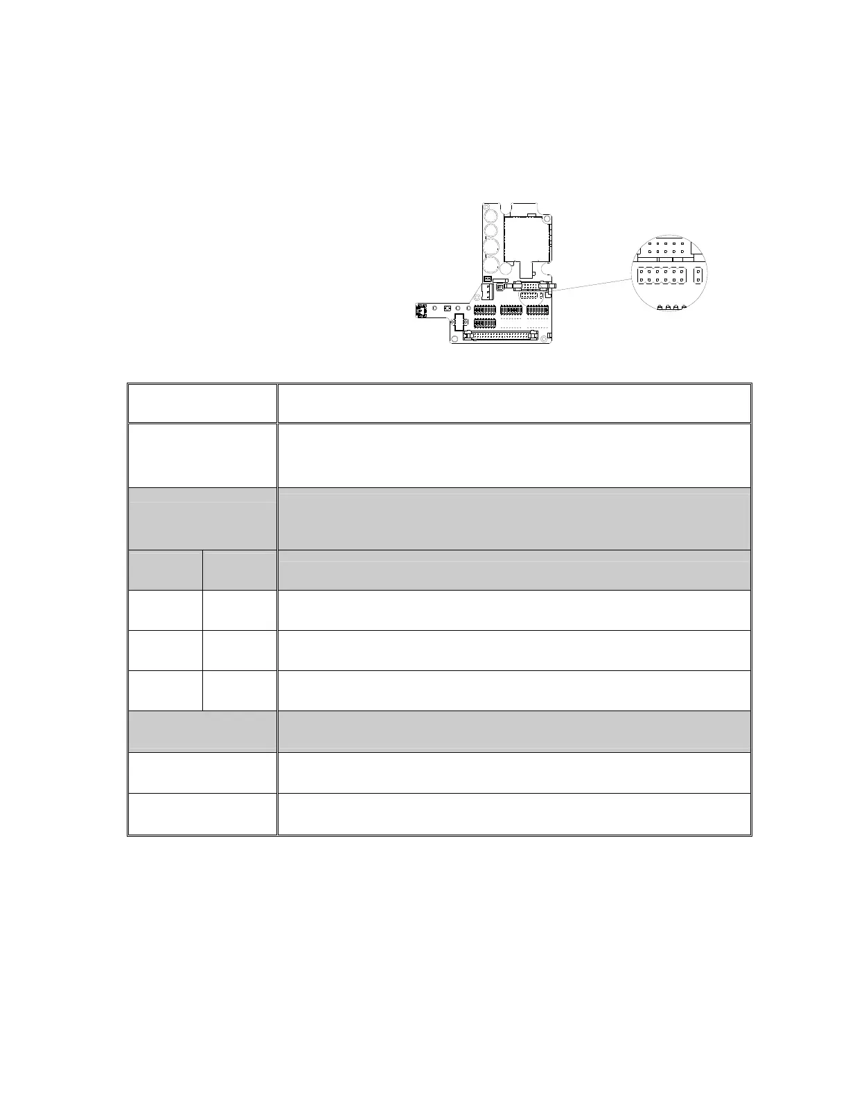
5. Jumper Settings
Jumper settings are applied to functions such as mainline-disconnect time, Start function,
transmitter push button layout, system information (serial number/ID code) programming and
system testing. The jumpers #1- #7 are located on the decoder module above the four (4) dip-
switches (refer to Fig.16 below).
(Fig. 16)
▇ Manufacture preset
Jumper Settings Function
JP3
(Blank)
After 1 or 3 minutes of transmitter inactivity (MAIN deactivated), press any
push button on the transmitter to reactivate the receiver MAIN.
JP3
(Inserted)
After 1 or 3 minutes of transmitter inactivity (MAIN deactivated), rotate the
transmitter power key-switch to “START” position to reactivate the receiver
MAIN.
JP4
(Blank)
JP5
(Blank)
Standard right-to-left push button configuration for all models.
JP4
(Inserted)
JP5
(Blank)
In-line push button configuration (top to bottom) for Flex 8ES/EX.
JP4
(Blank)
JP5
(Inserted)
In-line push button configuration (top to bottom) for Flex 12ES/EX.
JP4
(Inserted)
JP5
(Inserted)
In-line push button configuration (top to bottom) for Flex 4ES/EX.
JP6
(Blank)
Program system serial number/ID code and channel from decoder module
to I-CHIP.
JP6
(Inserted)
Program system serial number/ID code and channel from I-CHIP
to decoder module.
JP7
(Inserted)
For system test only, receiver MAIN disabled.