Flex 8EX EU System Instruction Manual
March 2012
1 of 37
Table of Contents
1. Introduction ............................................................................................................................................. 2
2. Radio Controlled Safety ......................................................................................................................... 3
3. General System Information .................................................................................................................. 4
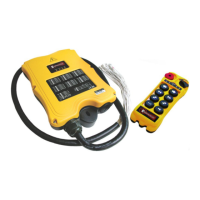
A. Transmitter Handset .............................................................................................................................. 4
1. External Illustration (Standard Push Button Configuration) ............................................................... 4
2. Internal Illustration .............................................................................................................................. 5
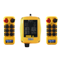
B. Receiver Unit ......................................................................................................................................... 6
1. External Illustration ............................................................................................................................ 6
2. Internal Illustration .............................................................................................................................. 7
4. Function Settings .................................................................................................................................... 8
A. Transmitter Handset .............................................................................................................................. 8
1. System Channel Settings .................................................................................................................. 8
2. Continuous Transmitting Time Adjustment ........................................................................................ 9
3. Push Button Functions with LED Displays ...................................................................................... 10
4. Channel Change via Push Buttons .................................................................................................. 14
5. Optional 4-Digit Security Code ........................................................................................................ 15
6. I-CHIP .............................................................................................................................................. 16
B. Receiver Unit ....................................................................................................................................... 17
1. System Channel Settings ................................................................................................................ 17
2. Output Relay Configurations ............................................................................................................ 18
3. Receiver Auto-Scanning Settings .................................................................................................... 21
4. Dip-Switch Settings .......................................................................................................................... 22
5. Jumper Settings ............................................................................................................................... 24
6. I-CHIP Programming Port ................................................................................................................ 25
7. Voltage Settings ............................................................................................................................... 25
5. System Channels Table ........................................................................................................................ 26
6. Receiver Installation ............................................................................................................................. 27
A. Output Relay Contact Diagram ........................................................................................................... 27
B. Pre-Installation Precautions ................................................................................................................ 28
C. Step-by-Step Installation ..................................................................................................................... 28
D. System Testing .................................................................................................................................... 29
7. Operating Procedure ............................................................................................................................ 30
A. Transmitter Operation ......................................................................................................................... 30
1. General Operating Procedure .......................................................................................................... 30
2. A/B Selector Push Button Operating Procedure .............................................................................. 31
3. 3
rd
Speed Push Button Operating Procedure .................................................................................. 31
4. Pitch & Catch Operating Procedure ................................................................................................. 32
5. Automatic Channel Scanning Operating Procedure ........................................................................ 32
6. Changing Transmitter Batteries ....................................................................................................... 32
B. Status Light Indicators & Warnings ..................................................................................................... 33
1. Transmitter STATUS Light Indication ............................................................................................... 33
2. Receiver STATUS Light Indication ................................................................................................... 34
3. Receiver SQ Light Indication ........................................................................................................... 34
4. Receiver POWER Light Indication ................................................................................................... 34
5. Receiver COM Light Indication ........................................................................................................ 34
C. Troubleshooting Tips ........................................................................................................................... 35
8. System Specifications .......................................................................................................................... 36