Flex 8EX EU System Instruction Manual
March 2012
10 of 37
52134 867
FUNCTION
LED 1LED 2LED 3LED 4
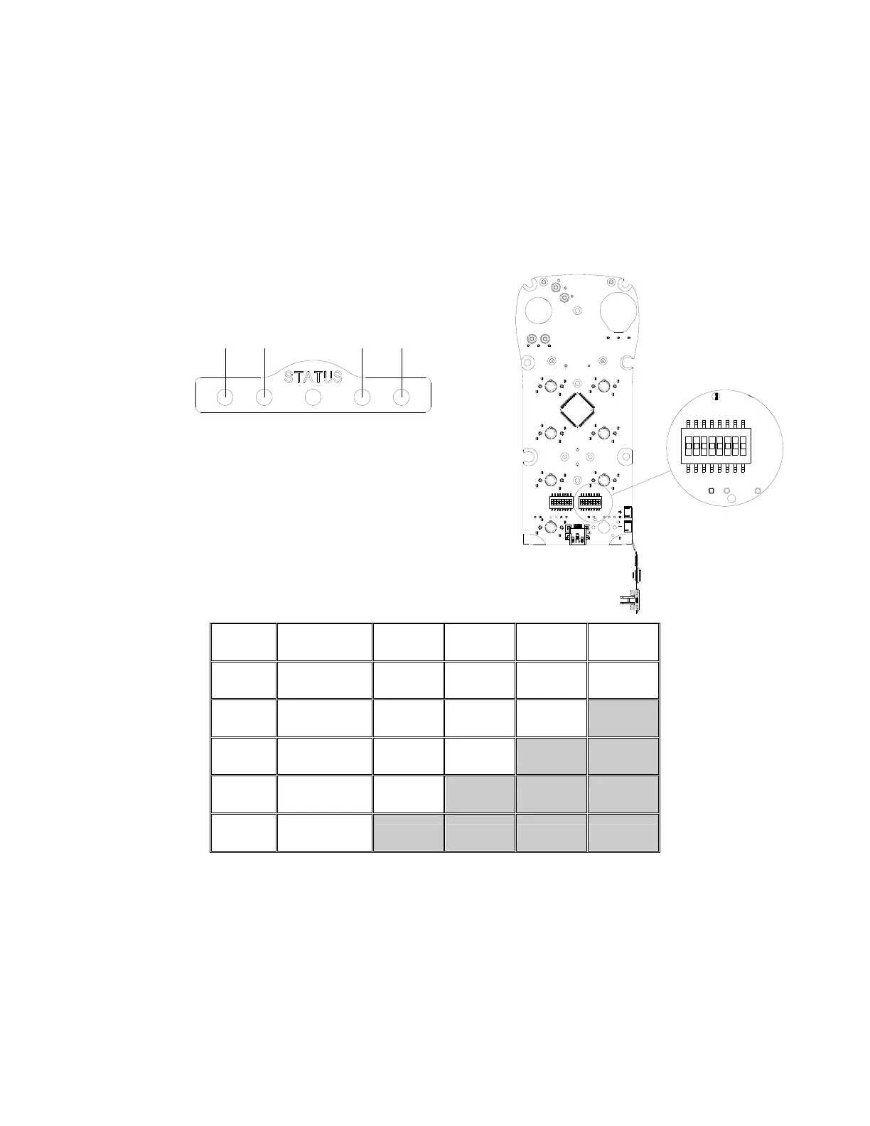
3. Push Button Functions with LED Displays
a. Standard Push Button Configuration (Transmitter Toggle)
Set the transmitter toggle (latching output relay) function by adjusting the 8-position
function dip-switch located on the backside of the transmitter encoder board (refer to Fig.
09 below). The LED 1 through LED 4 shown inside the shaded box (see below) illustrates
which LED on the transmitter will light up when the designated push button (PB5 - PB8)
is pressed.
(Fig. 09)
DIP PB5 PB6 PB7 PB8
1
00000000 Normal Normal Normal Normal
2
00000101 Normal Normal Normal
LED 4
3
00000110 Normal Normal
LED 3 LED 4
4
00000111 Normal
LED 2 LED 3 LED 4
5
00001000
LED 1 LED 2 LED 3 LED 4
* PB5…PB8 → Push button number
* Normal → Normal momentary contact
* LED 1…LED 4 → Transmitter toggled with designated LED Display