99
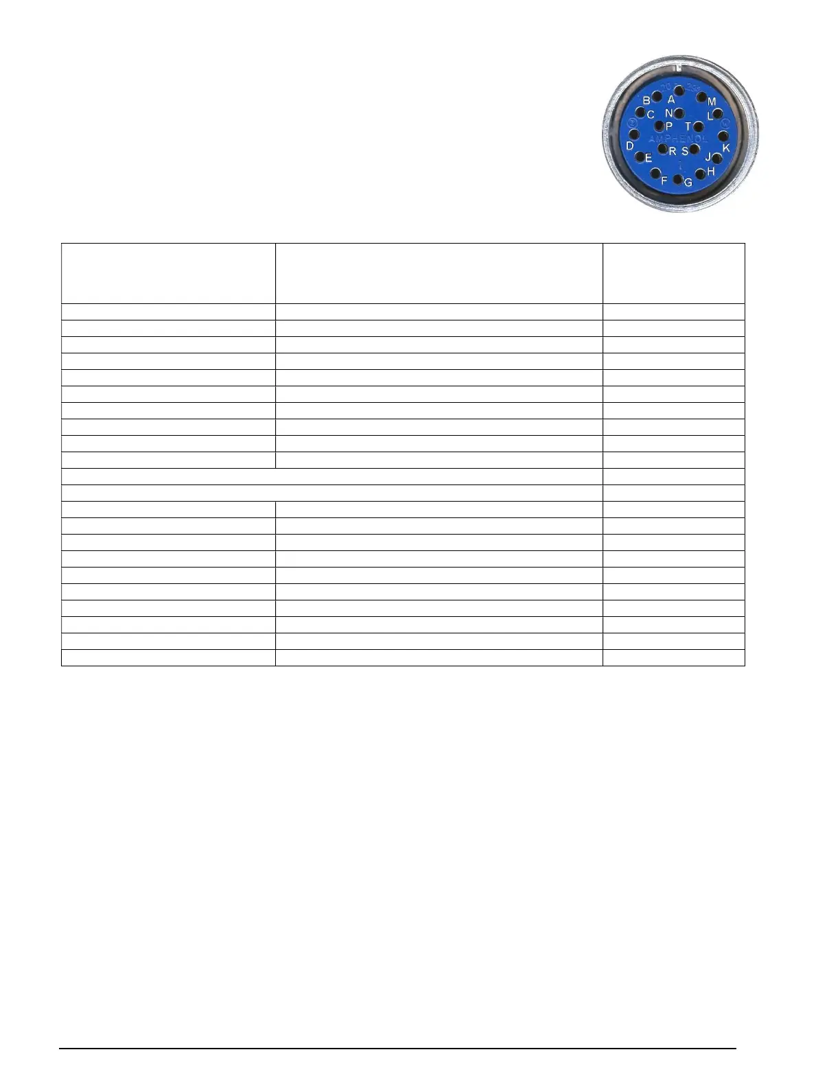
17 pin Amphenol connector Pin assignments
This table describes the pin assignment to device of the 17 pin
Amphenol connector with factory wire color assignment.
17 pin Amphenol connector
This pin goes to the
outside world through
this connector:
17 pin Amphenol connector
to drive this external device: wire color
pin A weigh bin dump air solenoid brown
pin B component 1 air solenoid orange
pin C component 2 air solenoid blue
pin D component 3 air solenoid gray
pin E component 4 air solenoid purple
pin M flow control air solenoid yellow
pin F component 7 air solenoid red
comp. 5
comp. 6
strobe and beeper + opt. alarm relay output
mix motor outlet, panel side
pin G comp. 8 - external SS relay wt./red
pin H comp. 9 - external SS relay wt./yellow
pin J comp. 10 - external SS relay wt./green
pin K comp. 11 - external SS relay wt./blue
pin L alarm
pin N common line, all outputs white
pin P comp. 12 - ext. relay (also air drive mixer)
pin R neutral to 10 volt signals (S,T)
pin S 0-10 volt extruder control signal
pin T 0-10 volt line speed control signal
External SS relays are optional.
External SS relays and air solenoids may be exchanged.
 Loading...