G-14
35 Series 4WD, Model - 3535, 4035, 4535 and 5035 SM June’08
Electrical System
NOTE: The Starting circuit is interconnected
with the Forward / Reverse system. Thus the
Engine will not start unless the Forward /
Reverse is in neutral.
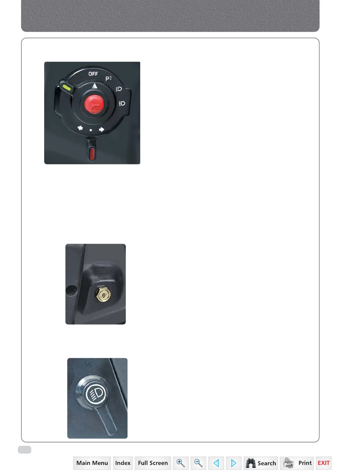
SWITCHES
Combination Switch:
It is located in LH side of steering column on dashboard.
It consists of:
1. Horn (in centre)
2. Light Switch
3. Turn Signal Switch
Horn
Pressing the horn switch will blow the horn.
Light Switch
It is a 4 positions rotary switch. It operates in clockwise
direction and positions are as follows:
1. Off
2. Illuminate Parking Lamp
3. Illuminate low beam of head lamp & Parking Lamp
4. Illuminate high beam of head lamp & Parking Lamp
Turn Signal Switch
This is 3 positions rotary switch. The vertical position of
knob operates in both directions and the positions are
as follows:
1. Vertical - OFF
2. Left - Operates LH Turn signal Lamp
3. Right - Operates RH Turn Signal Lamp
Starter Key Switch
It is a key operated 3 positions rotary switch. It is
located in RH side of steering column on dashboard.
It operates in clockwise direction and positions are as
follows:
1. Off
2. It gives readiness to electrical circuit for operation
of plow lamp switch, combination switch,
instrument cluster.
3. Activates the starting circuit for engine.
Plow Lamp Switch
It is a 2 positions rotary switch located in LH side of
steering column on dashboard. It operates in clockwise
direction and positions are as follows:
1. Off
2. Illuminates the plow lamp
 Loading...


