I-26
35 Series 4WD, Model - 3535, 4035, 4535 and 5035 SM June’08
Hydraulics
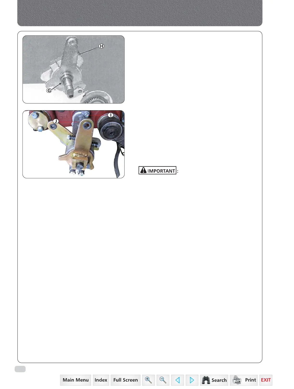
5. Remove snap ring (G) and lever draft
control (H).
6. Remove support (J) by loosening set screw (I).
7. Loosen socket head screws on clutch hubs
and remove clutch hubs and nylon bushings
(2 nos).
8. Inspect nylon busing for excessive wear or
cracks. Replace as necessary.
9. Clean and inspect all parts for wear or damage.
Replace as necessary.
Always use new O’rings. Used or
damaged O’rings will leak.
Protruding side of clutch hub fits between tabs on
control lever.
10. Install nylon bushings into clutch hubs and
install hubs to control lever and pitman arm.
Hand tighten adjusting screw.
11. Install new O’ring onto shaft and apply
multipurpose grease on shaft.
12. Install support over shaft and tighten two
screw.
13. Install new O’ring on lever draft control.
14. Install lever draft control into support.
15. Install snap ring in groove of shaft.
16. Install hub to lever draft assembly using cap
screw.
17. Install lever position control using socket head
screw.
18. Install linkages levers to control levers and
secure with lock clips.
19. Install lift unit.
20. Adjust hydraulic control lever friction.
 Loading...


