S = Overhang from rear axle of the machine (cm).
S1 = Distance of rear axle from parallel hitch (cm).
S2 = Distance between bar hitch hole and center of gravity of machine (cm) (Fig. 11).
3.6 PROPELLER SHAFT
Propeller shaft adaption
The Propeller shaft, supplied with the machine, is of standard length. Therefore it might be necessary to adapt the
Propeller shaft.
In that case, before doing anything, consult the Manufacturer for the eventual adaptation.
Hitch the machine to the tractor and stabilize the tractor's third point with the device installed for that purpose (bar,
chain, etc.).
Disengage the tractor's PTO and turn off the engine.
Connect the driveline shaft to the tractor's PTO.
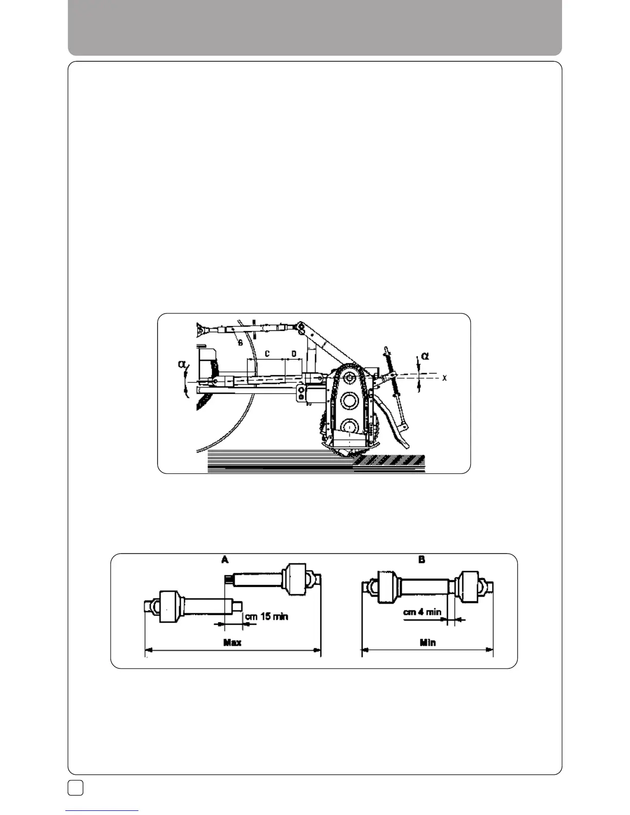
Connection is correct when the machine is horizontal in the operating position.
To achieve this, increase or decrease the length of the top bar of the hitch (B Fig. 12) so as to set the axis (X Fig. 12)
of the housing's grooved ring nut parallel to the ground.
20
Inspections at work:
- The two angles formed by the fork axes and the axis of the sliding tubes will be equal and must not exceed 10°.
- The sliding tubes (A Fig. 13) must overlap by at least 15 cm (Fig. 13).
Inspections in the raised position:
- Proceed with a lifting action (tractor PTO disengaged).
- The two tubes of the driveline shaft must not fully overlap. There must always be a safety travel (B Fig. 13) of at
least 4 cm.
- The angles of the drivelines must not exceed 40°.
If these two results are not obtained:
3.0 USE INSTRUCTIONS
Fig. 12
Fig. 13
 Loading...