Once the rollers (3) are
duly positioned, tighten the knob (4) to lock position.
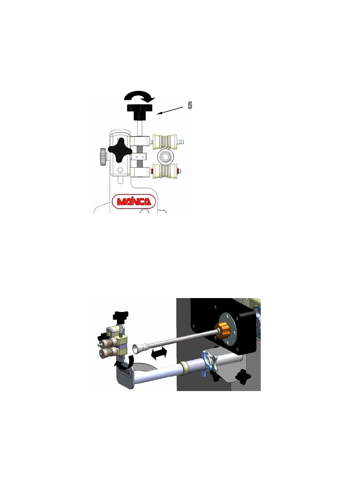
Finally, set the distance between upper and lower roller by means of the top knob (5).
Screw the knob (5) if you need to separate the 2 rollers or unscrew it if you need to
approach them. The gap between upper and lower roller should be smaller than the
outer diameter of the silicon tip (X) to ensure the rollers will hold the casing tight
enough to be twisted. (see fig. 13).
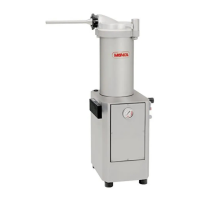
Both rollers can be ind
ependently moved aside by hand (90º) to ease the reload of
casing or change of the silicon tip / nozzle. (see fig. 14). Remove the silicon tip by
pushing out before loading the nozzle with more casing. Push the silicon tip into the
nozzle once the casing is loaded.
This mechanism has a self tightening spring. Rollers are loose when they are moved
aside and keep tight when they are in front of the silicon tip and nozzle.
fig.13
fig.14