Figure 6.4
Note: If the steering system needs repair, your
Mainship dealer has the correct tools. Do not try to ser-
vice the system yourself.
Parts List for Fig. 6.4
1. Auto Pilot
2. Tiller Arm
3. Tie Bar
4. Rudder Shaft and Seal
5. Hydraulic Hoses
6. Steering Ram
Figure 6.5
Parts List for Fig. 6.5
1. Auto Pilot (See OEM manual)
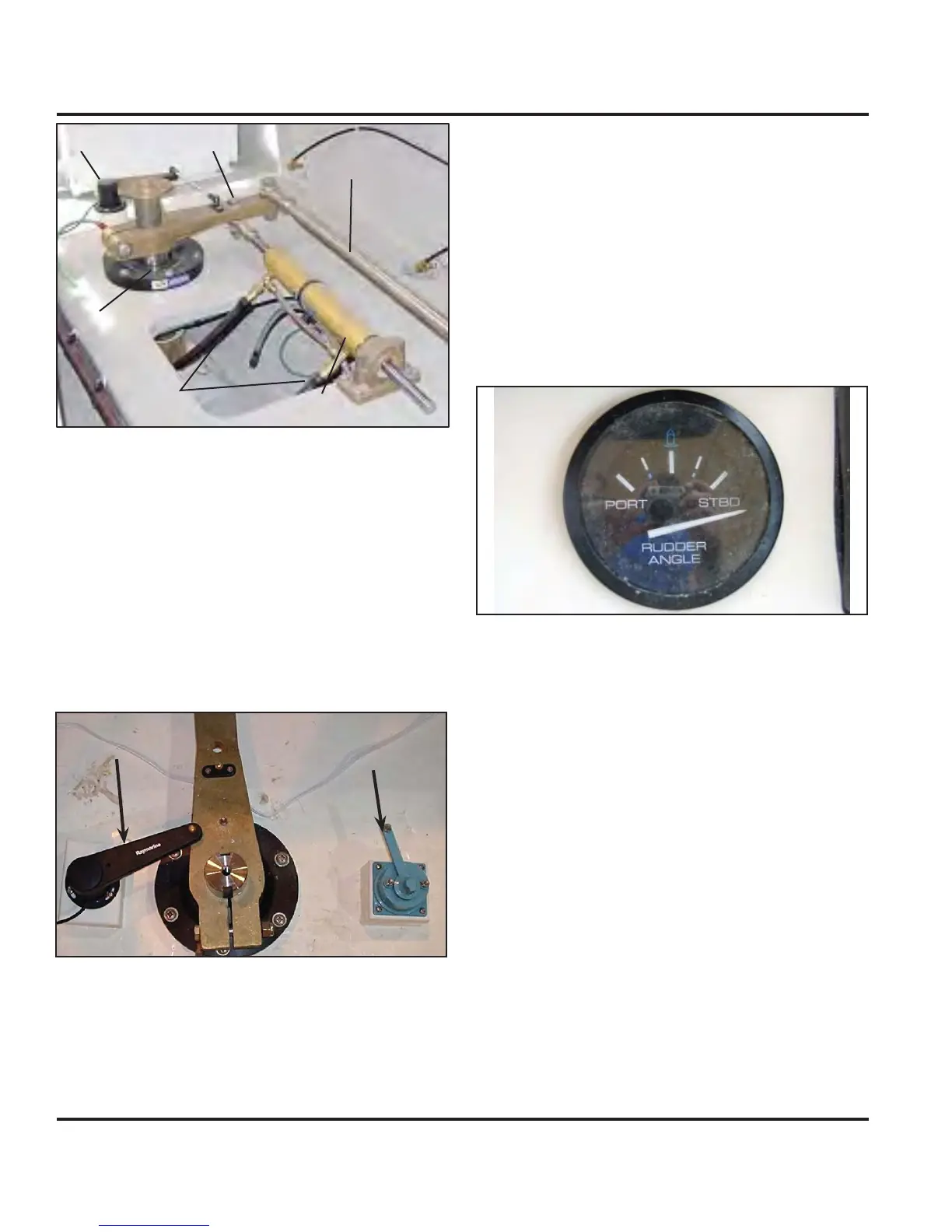
2. Rudder Position Indicator (Optional)
The rudder position indicator consists of two parts: the
sender which is attached to the tiller arm in the transom
area, and the gauge indicator which is at the helm sta-
tion.
The gauge indicator will move to either the port or the
starboard side of the gauge in relation to the movement
of the rudder arm.
Figure 6.6
6.2.2 Rudders
Your Mainship 34 Trawler Hardtop has a manganese
rudder. The rudder shaft stuffing box provides an open-
ing for the rudder shaft through the bottom of the boat.
The stuffing box keeps water from leaking around the
shaft into the boat. These also use a “dripless” stuff-
ing box. However because the friction involved in the
shaft seal is not evident in the rudder shaft no coolant
is needed to keep the bearings cool. On the following
page you will find a breakdown of the components that
make up the rudder assembly.
(Optional) Autopilot
The autopilot works much the same way as the posi-
tion sensor in that it has a sensor at the tiller arm which
controls the autopilot keeping the boat on the course
programmed to the controls.
For more information about the autopilot consult your
documentation in your owner’s packet.
Auto Pilot
Position Sensor
12
3
4
5
6
Mainship 40 Trawler Single & Twin • Underwater Gear
6.4
 Loading...