ainship 40 Trawler Sin
le & Twin • DC Electric S
stems
7.
C Electric S
stem
Your boat has a 12 V DC ne
ative
round and a 120V
z
Hertz
A
electrical s
stem. Your electrical s
stem
was thorou
hl
inspected at the factor
before
our boat
was delivered to
our dealer. The DC Electric S
stem
onsistso
the
ollowin
s
stems or components
Batter
Switches
Distribution Panel
lm
ntr
l
tt
r
Batter
har
er
umps
t
n
Monitors
aste S
stems
En
ine Controls
Bil
e Blowers
ppliances
n
Trim T
au
es
7.1 DC Power S
stem & Components
o operate the 12V DC S
stem
1. Switch the main batter
switch in the en
ine com-
artmrnt to
N.
2.
wit
h th
D
MAIN
ir
it
r
k
r
t th
D
istribution Panel to
N.
ote: Alwa
s switch circuit breakers off when
ou leave
our
oat unatten
e
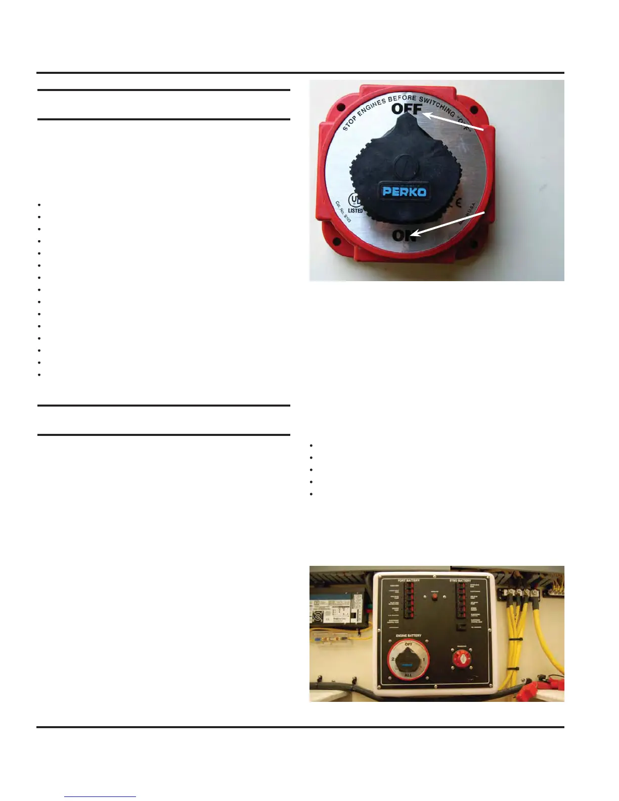
7.1.1 Batter
Switche
Each batter
bank is wired to a batter
selector switch
Fi
. 7.1
located on the en
ine room aft bulkhead. The
batter
switch controls the deliver
of DC power from
the batteries to the en
ine and all components usin
D
w
Off position
On position
Fi
ure 7.1 Batter
Switch
7.1.2 Batter
Switch Panel
The batter
switch panel supplies power to all the ma
or
s
stems of
our boat, as well as controllin
power to the
constant hot" s
stems. These are s
stems that need o
have power supplied to them whether the batter
switch
i
n
r
ff
Note: For safety and convenience the following items are not
shut off by the battery switches:
e
umps
ump Pum
Monitor
tereo Memor
En
in
These items need constant power to perform their task.
This allows the bil
e pumps to operate an
time excess
luid accumulates in the bil
e. The remainin
D
s
stem
is turned off with batter
switches.
Fi
ure 7.2 Batter
Switch Panel
 Loading...