ainship 40 Trawler Sin
le & Twin • DC Electric S
stems
7.4
of
ellow
ne
ative
wires attached. All electrical circuits
require a
round, so all
rounds are
oined in sections at
roundin
blocks”.
You will notice on the ri
ht hand side of the
roundin
block pictured a
reen wire attached, this is part o
the
Bondin
S
stem”.
The purpose of the bondin
s
stem is to protect
ou
boat’s underwater components
rom electrol
sis or
al-
vanic corrosion. Examples of underwater components
would be the
ro
ellers,
ro
eller shafts, rudders, o
n
ine
enerator and seawater intake valves
ectro
s
s an
a
van
c corros
on occurs pr
mar
n
alt water but can occur to a lesser de
ree in
resh water.
lt w
t
r
ll
w
l
tri
rr
nt t
fl
w fr
m
n
i
t
athodic material. An
two metals from two components
and their relative position in the
alvanic ratin
table
will determine which metal loses material
anode
and
which metal remains lar
el
undisturbed
cathode
. The
distance apart in the
alvanic table o
the two metals
t
rmin
th
r
t
f w
r.
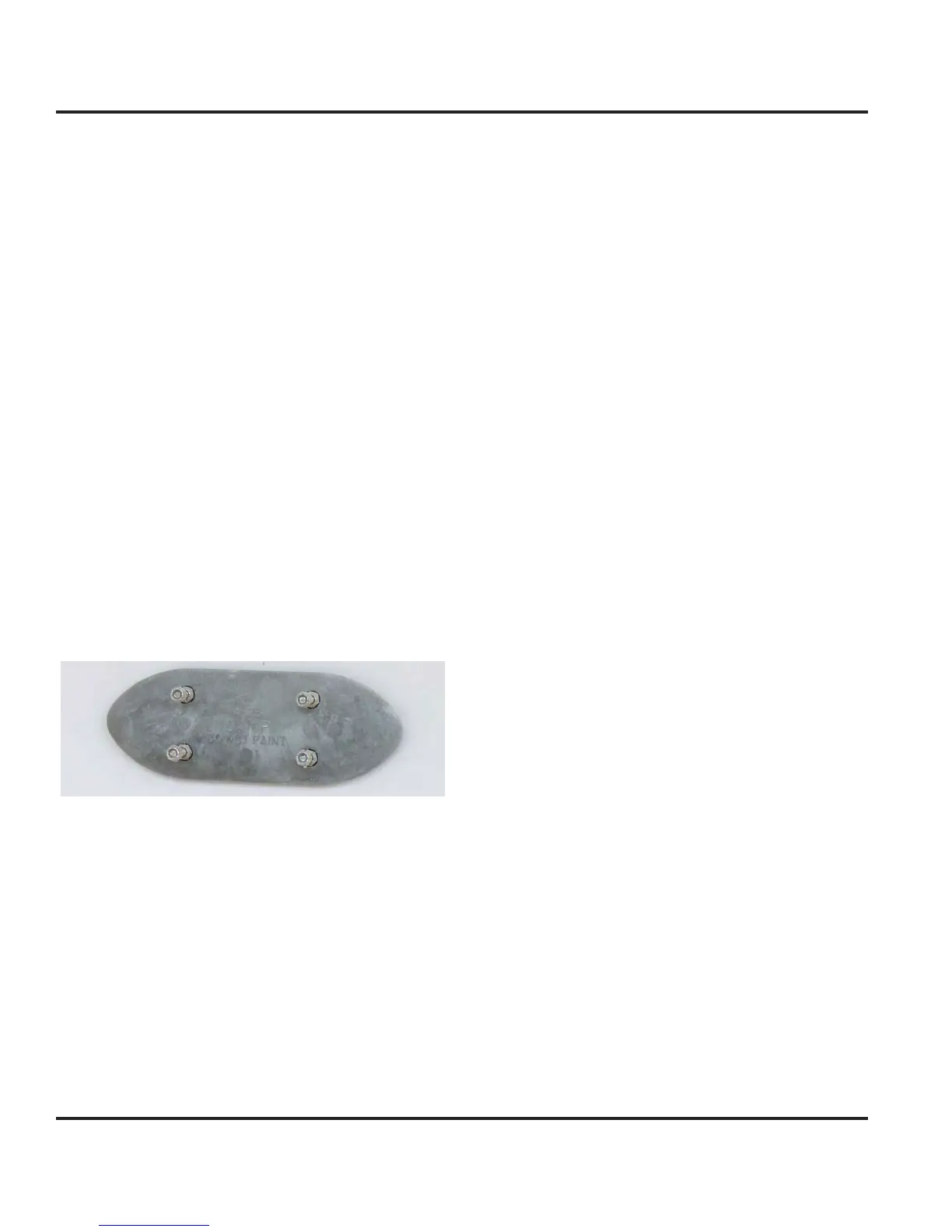
To help prevent corrosion, sacri
icial zinc anodes are
wired to the underwater components of
our boat, such
as the
ro
eller shafts and rudders, then connected to a
lar
e sacri
icial zinc anode plate
i
. 7.5
attached to the
n
rw
t
r
r
th
tr
n
m
ure 7.5
nc
at
The sacrificial zinc anodes are considerabl
easier and
hea
er to re
lace and their deterioration will not affect
the per
ormance o
our boat as would the deterioration
of an
underwater components.
The bondin
s
stem is a network o
wires
color coded
reen
that are connected to all metallic underwater com-
onents within the interior of the hull, which makes them
one unit
or electrical current purposes. This network o
wir
i
th
n
tt
h
t
th
ri
i
i
l zin
n
l
t-
d on the transom, which allows corrosion of the anode
but prevents corrosion o
the underwater components.
General maintenance of the bondin
s
stem consists o
earl
replacement of the sacrificial anodes. This should
be completed durin
the sprin
launch procedure
o
xample. The anode ma
require more frequent replace-
ment,
epen
n
on
our
oc
n
ocat
on an
t
e
en
t
o
our boatin
season. I
possible, check the anode
o
xcessive corrosion midwa
throu
h
our boatin
sea-
on. If excessive corrosion is noted, have
our dealer o
a competent technician replace the sacri
icial zinc anode.
eriodicall
check the wirin
connections to make sure
the
are ti
ht and free of corrosion. Ti
hten and clean
onnections as necessar
Important: DO NOT PAINT any part of the sacrificial zinc
anode as it will retard the flow of electric current through
them and render them ineffective.
7.1.7 Generator
Althou
h technicall
the
enerator is part of the AC
stem, because it supplies A
power. The startin
o
the
enerator requires DC power, the
enerator startin
receives
ower from the batteries in the lazarette area.
The
enerator supplies 120 volt 60 hz AC power fo
operat
n
ev
ces an
equ
pment contro
e
t
rou
t
e
A
Distrbution Panel.
When the
enerator indicatin
li
ht is on and the
enera-
tor breakers are
N, A
power is supplied to both the
enerator and AC control panel devices and equipment.
The
N li
ht at the A
Distribution Panel is
ill
min
t
.
The slide bar prevents power
rom bein
supplied
rom
hore power when usin
the
enerator
e
er to the
peration and Procedures” part o
the A
Electric section
or in
ormation on startin
the
enerator.
7.1.8 DC Distribution Panel
The DC Distribution Panel, located in the starboard aft
ide o
the salon controls D
current throu
hout the boat.
Fi
ure 7.8 lists the breakers and circuits the
protect.
Besides the batter
selector switches
ou must en
a
e
the D
Main at the MDP to provide D
power to the
respect
ve components or s
stems.
 Loading...