ainship 40 Trawler Sin
le & Twin • DC Electric S
stems
7.
CAUTION
! !
Fuel fumes in the en
ine compartment can explode.
Before workin
on electrical wirin
ventilate en
ine room
n
sconnect
atter
ca
es to prevent spar
s.
There is an exhaust blower installed in the head, con-
tro
e
a sw
tc
n t
e
ea
.
The en
ine room blower is an exhaust fan which will
remove an
exhaust fumes from the en
ine room, as
well as removin
heated air.
e
ower
n t
e
azarette area, or
enerator space
s a
uppl
an. It supplies
resh air to the
enerator
option
.
This blower fan is specific to the
enerator and will onl
be installed if the
enerator option is ordered.
7.2.12 Fire Extin
uishin
S
stems
Another component that is speci
ic to the
enerator is
the fire extin
uisher in the lazarette area. If
our boat
oes not
ave t
e
enerator opt
on t
en t
s s
stem
s
n
t in
t
ll
.
In the en
ine room there is another fire extin
uishin
bottle installed. This s
stem is D
powered, with the
rela
, or “module” and the alarm at the helm station.
When a fire is detected on
our boat, the alarm will sound
and set o
the Halon bottles. This rela
will shut down
the en
ines, the blowers, and the
enerator. To reset the
stem, act
vate t
e reset sw
tc
on t
e mon
tor at t
e
helm.
ee
i
. 7.1
Fi
ure 7.11 Fire Alarm Monito
7.2.13 Shower Sum
The shower sump is part o
the
anitar
stems and
more in
ormation about the
hower
ump can be
ound
in that section, however the breaker control for the show-
our safet
The horns are D
powered and the controls are located
t th
h
lm.
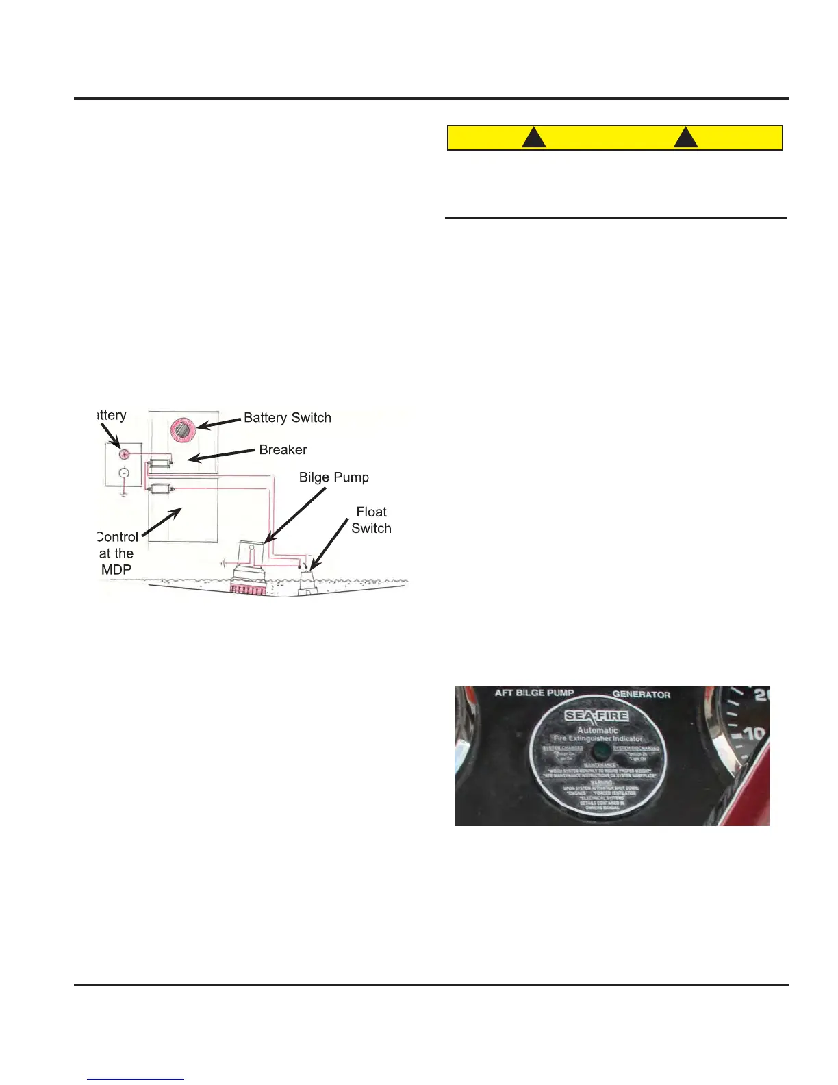
7.2.10 Bil
e Pump S
stem
The Mainship 40 Trawler is equipped with 3 bil
e pumps
and one emer
enc
bil
e pump. For locations of the bil
e
pump s
stems consu
t
our
ec
an
ca
rran
ement
rawin
or the
anitar
stems Drawin
.
The Bil
e Pump S
stem consists of a pump and a float
witch. When the water level rises
ar enou
h to activate
the float switch this activates the pump which lowers the
water level down to a
oint that the float switch sto
s the
power. Fi
. 7.10 shows
ou the t
pical wirin
.
Fi
ure 7.10 Bil
e Pump S
stem
7.2.11 Ventilation
entilation is a ver
important issue with
our boat, with
the potential
or carbon monoxide buildup
see Boatin
afet
Section
alon
with the simple comfort of fresh
air or air conditionin
, ventilation is a standard that is a
necessit
n
our Mainship 40 Trawler there are essentiall
three
t
pes o
ventilation, the air conditionin
s
stem
A
stem
, the exhaust or blowers, and the Bomar hatches,
which suppl
ou with
resh air when opened.
ince the
air conditionin
s
stem is A
powered
see A
Electric
ection
and the hatches require no power we will detail
the blowers
or exhaust
ans
, and their
unction here
or
ower
ocat
on consu
t
our
ec
an
ca
rran
ement
Illustration in the Boatin
a
et
ection, or the Ventilation
Ill
tr
ti
n in th
m
ti
n.
B
 Loading...