Repair
P 10 / 14
[11] Disassembling Armature
1. With referring to the following section, disassemble Handle R and Gear housing cover.
[4] Disassembling Handle section in page 3
[5] Disassembling Gear housing cover section in page 4
2. Keep Brush holders away from the near side of Commutator. (Disconnecting the electrical parts is not required.)
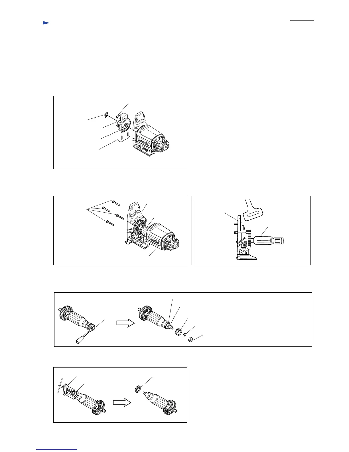
3. Remove Retaining ring S-8, and separate Crank complete, Balance plate and Gear complete from the shaft of Gear
housing as illustrated in Fig. 32.
Note: It is not necessary to remove M4x12 Hex socket head bolt, Crank complete and Gear complete from Balance plate.
Be careful not to lose Needle bearing 407.
Retaining
ring S-8
Crank complete
Needle bearing 407
Balance plate
4. Remove four 4x30 Tapping screws, and then separate Gear housing from Motor housing. (Fig. 33)
Separate Armature from Gear housing by striking Gear housing with plastic hammer. (Fig. 34)
4x30 Tapping
screws
Gear housing
Gear housing
Armature
Armature
Motor housing
Gear complete
Fig. 32
Fig. 33 Fig. 34
5. Remove Self lock 6 with slotted screwdriver. Magnet sleeve, Wave washer 6 and Rubber ring 19 are removed from
Armature shaft. (Fig. 35)
6. Remove Ball bearing 607LLB from Armature shaft. (Fig. 36)
*Self lock
*Magnet sleeve
*Wave washer 6
Rubber ring 19
Ball baring 607LLB
Insulation washer
Fig. 35
*It is not used for model 4350T.
Ball bearing
607 LLB
Insulation washer1R269
Fig. 36
 Loading...