Wiring diagram
P 6/ 8
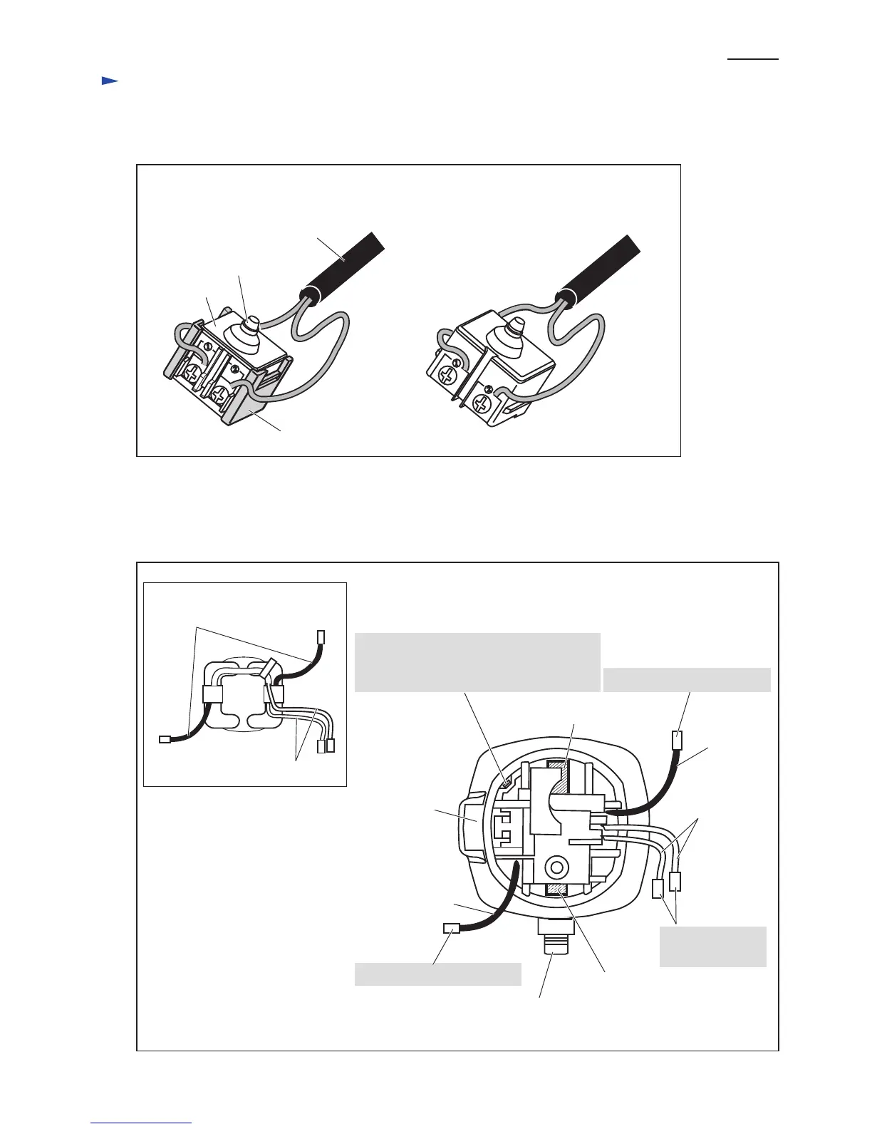
Fig. 12
[When Spacer is used] [When Spacer is not used]
Spacer
Switch
Switch button
Power supply cord
[1] Connecting Lead Wires of Power Supply Cord with Switch
Connect the lead wires with Switch as illustrated in Fig. 12.
(view from Rear cover side)
Switch lever
Earth terminal on the lead wire (clear)
of Noise suppressor* has to be connected
to this portion.
Route Field lead wires as illustrated in Figs. 13 - 16.
[2] -1. Rear End
Brush holder A
Brush holder B
[Motor Housing with Field]
Spindle
Connect to Brush holder B.
Connect to
Switch terminals.
Lead wire
(black)
Lead wire (black)
[Lead Wires of Field]
[2] Wiring of Field Lead Wires in the Rear of Motor Housing
Fig. 13
Lead wire (white)
Lead wire (black)
Field
Lead wire (white)
*Some countries do not use noise suppressor.
Connect to Brush holder A.

 Loading...