EasyManuals Logo

Makita 9558HN Technical Information

Makita 9558HN
8 pages
To Next Page IconTo Next Page
To Previous Page IconTo Previous Page
Page #7 background imageLoading...
Page #7 background image
Wiring diagram
P 7/ 8
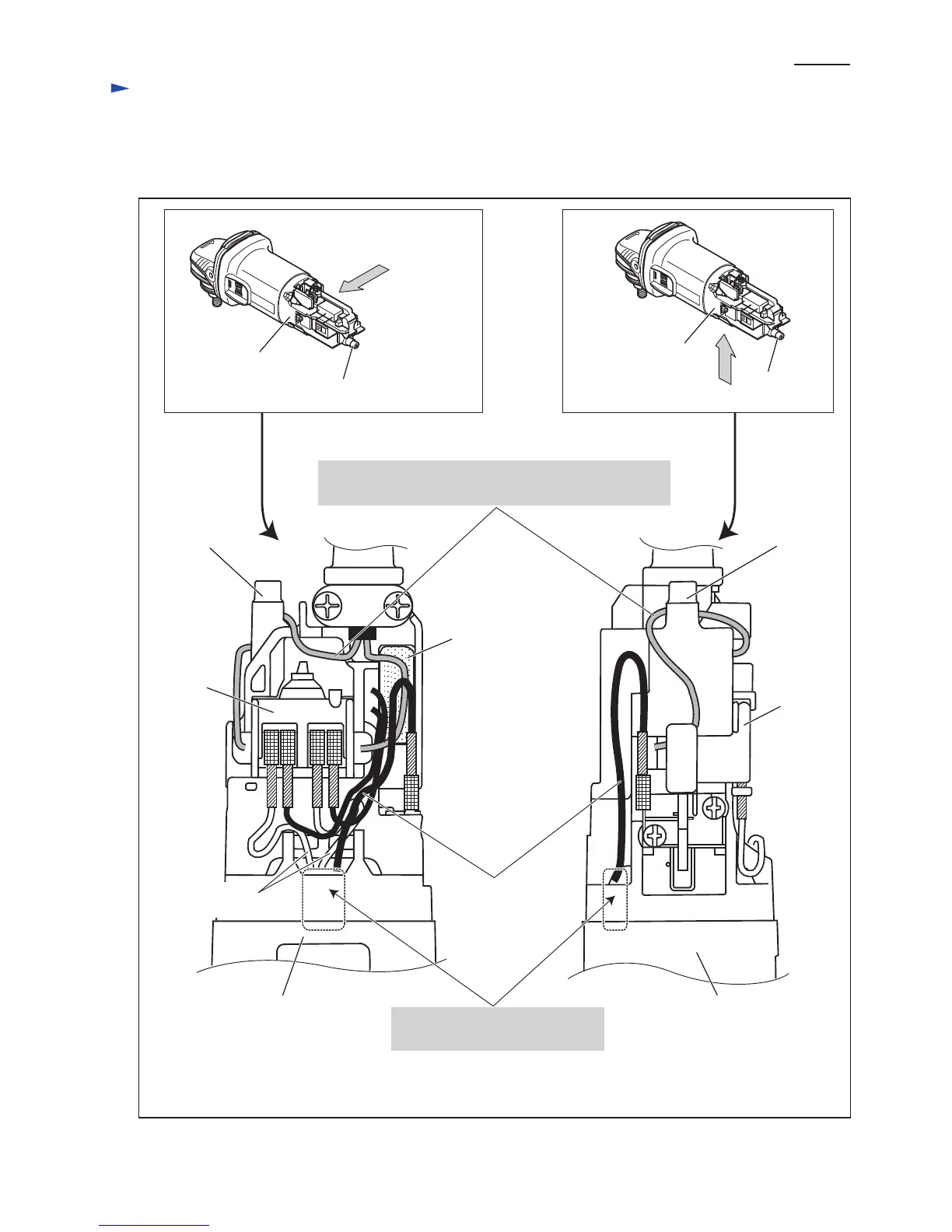
[2] -2. Right Side and Bottom
[2] Wiring of Field Lead Wires in the Rear of Motor Housing (cont.)
Fig. 14
Noise suppressor*
Right side view
Switch
Switch
Boss A Boss A
Boss A
Field lead wires
(white)
Field lead wire
(black)
*Some countries do not use noise suppressor.
Route the lead wire of Power supply cord to
Switch terminal No.2 so that it runs around the boss A.
Motor housing
Bottom view
Motor housing
Boss A
Make sure that Field lead wires
are tight in Motor housing.
Motor housing,
viewed from bottom
Motor housing,
viewed from right side

Other manuals for Makita 9558HN

Questions and Answers:

Question and Answer IconNeed help?

Do you have a question about the Makita 9558HN and is the answer not in the manual?

Makita 9558HN Specifications

General IconGeneral
Input power840 W
Cable length2.5 m
Power sourceAC
Spindle threadM14
Idle speed (max)11000 RPM
Grinding disc diameter125 mm
Product colorBlack, Green, Silver
Weight and Dimensions IconWeight and Dimensions
Width139 mm
Height106 mm
Length271 mm
Weight2100 g

Related product manuals