P 11/ 19
Repair
[3] DISASSEMBLY/ASSEMBLY
[3]-5. Crank section, Gears (cont.)
DISASSEMBLING
DISASSEMBLING
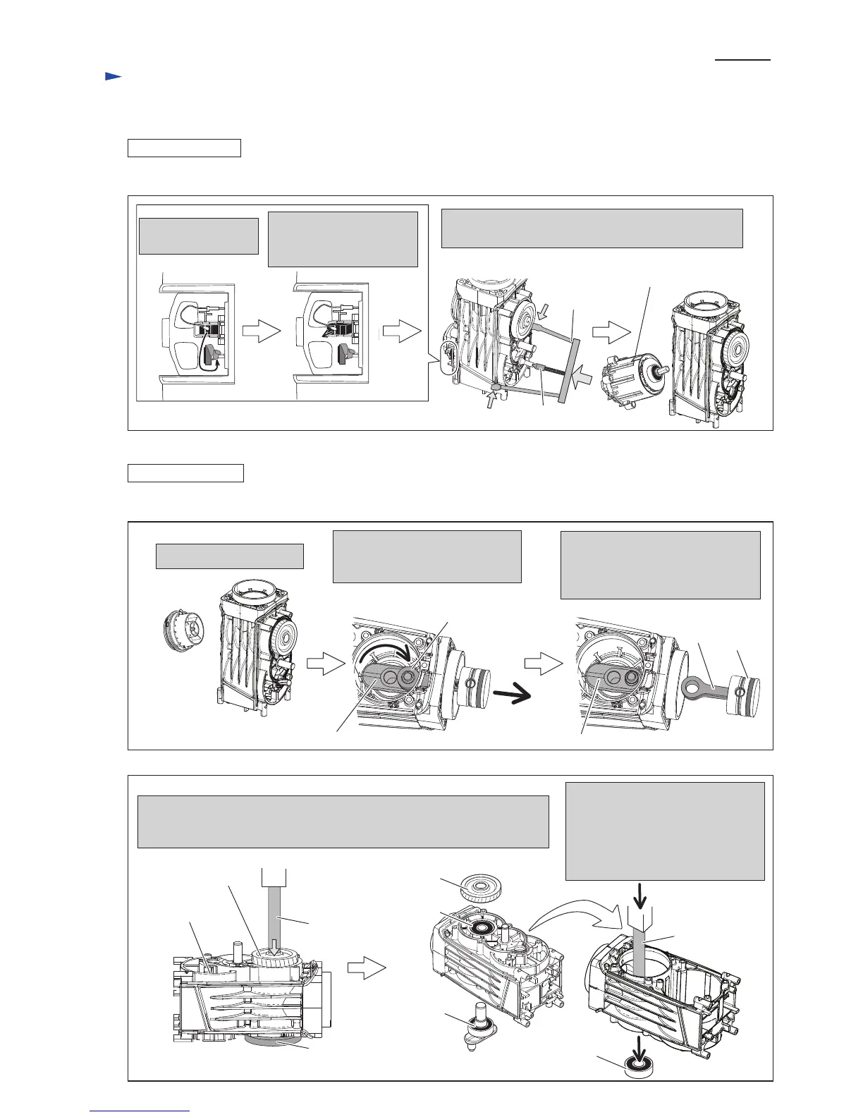
(4) Disassemble Armature as illustrated in Fig. 20.
1. Disassemble Crank cap.
2. Set Crank shaft and Connecting
rod of Piston to the position
illustrated below.
Fig. 20
(HM1307C, HM1307CB without AVT mechanism)
(5A) Disassemble Crank section as illustrated in Figs. 21A and 22A.
Fig. 21A
Fig. 22A
1R217
Helical gear 47
Connecting rod of Piston
Crank shaft
Crank housing
complete
Crank shaft
Ball bearing
6204LLB
Crank cap
4. Putting Crank housing complete on 1R217, press Crank shaft with Arbor
press. Crank shaft can be removed from Helical gear 47.
Ball bearing 6204LLB still remains in Crank housing complete.
Detach Spiral spring
from Carbon brush.
By pulling Carbon brush,
disconnect its contact with
Armature's commutator.
1R045
Disassemble Motor section (Motor housing, Armature,
Field, Brush holder unit etc.) using 1R045 with 1R346.
1R346
3. Piston can be pulled off from
Connecting rod.
O rings on Piston can be replaced.
See Fig. 19.
Piston
Connecting
rod
1R246
Motor section
1R252
5 Inserting 1R252 from the Crank
shaft side, press the 1R252 with
Arbor press.
Ball bearing 6204LLB can be
disassembled from Crank housing
complete.
Helical gear 47
Crank shaft
Ball bearing
6204LLB
 Loading...