P 12/ 19
Repair
[3]-5A. Crank section, Gears
(HM1317C, HM1317CB with AVT mechanism)
[3] DISASSEMBLY/ASSEMBLY
[3]-5. Crank section, Gears (HM1307C, HM1307CB without AVT mechanism)
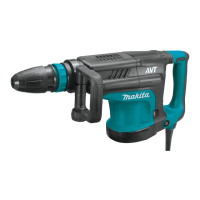
DISASSEMBLING
1. Remove Crank cap cover,
levering up it with Slotted
head screwdriver.
And remove M6x30 Hex
socket head bolts.
2. Twist the Slotted head screw drivers
inserted into the gap between Bearing
box complete and Crank housing
complete. Bearing box complete can be
removed from Crank housing complete.
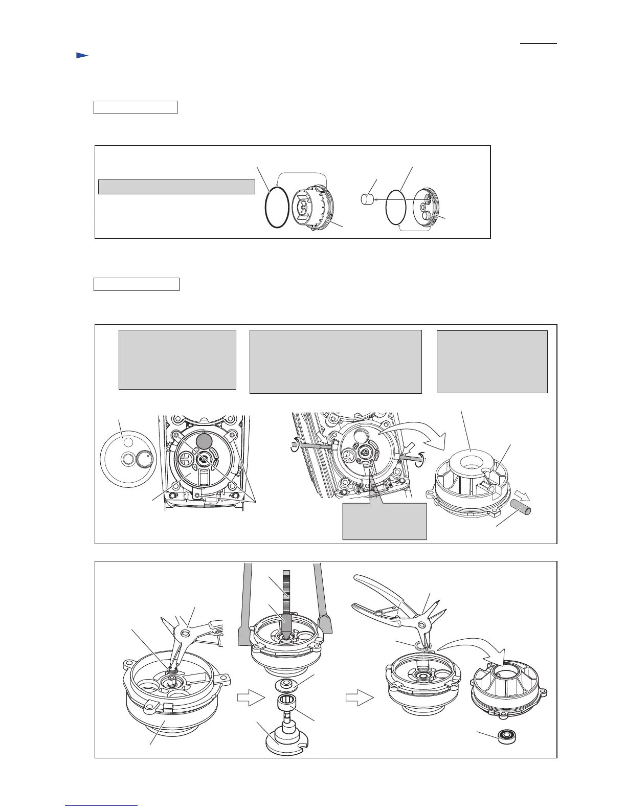
(5B) Disassemble Crank section as illustrated in Figs. 21B and 22B.
Fig. 21B
Fig. 22B
Retaining
ring S-8
Needle
bearing
1813
Ball bearing 608ZZ
Shoulder
washer 8
1R045
1R346
1R291
Crank cap
cover
Bearing box
complete
M6x30
Hex socket
head bolt (3pcs.)
Pay attention, not to lose
Pin 10 when removing the
Bearing box complete.
The Pin 10 is an important
parts for AVT mechanism.
Pin 10 is mounted
in the opposite side
of this part.
Pin 10
Bearing box
complete
Bearing box complete
Counter
shaft
Retaining
ring R-22
1R291
Counter shaft
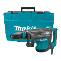
Fig. 23A
Crank cap
O ring 87
(6A) O rings on Crank cap and Crank cap cover, and Filter can be replaced. See Fig. 23A.
O ring 74
Crank cap section can be disassembled.
Crank cap
cover
Filter
DISASSEMBLING
 Loading...