[3] DISASSEMBLY/ASSEMBLY
[3]-1. Base (cont.)
DISASSEMBLING
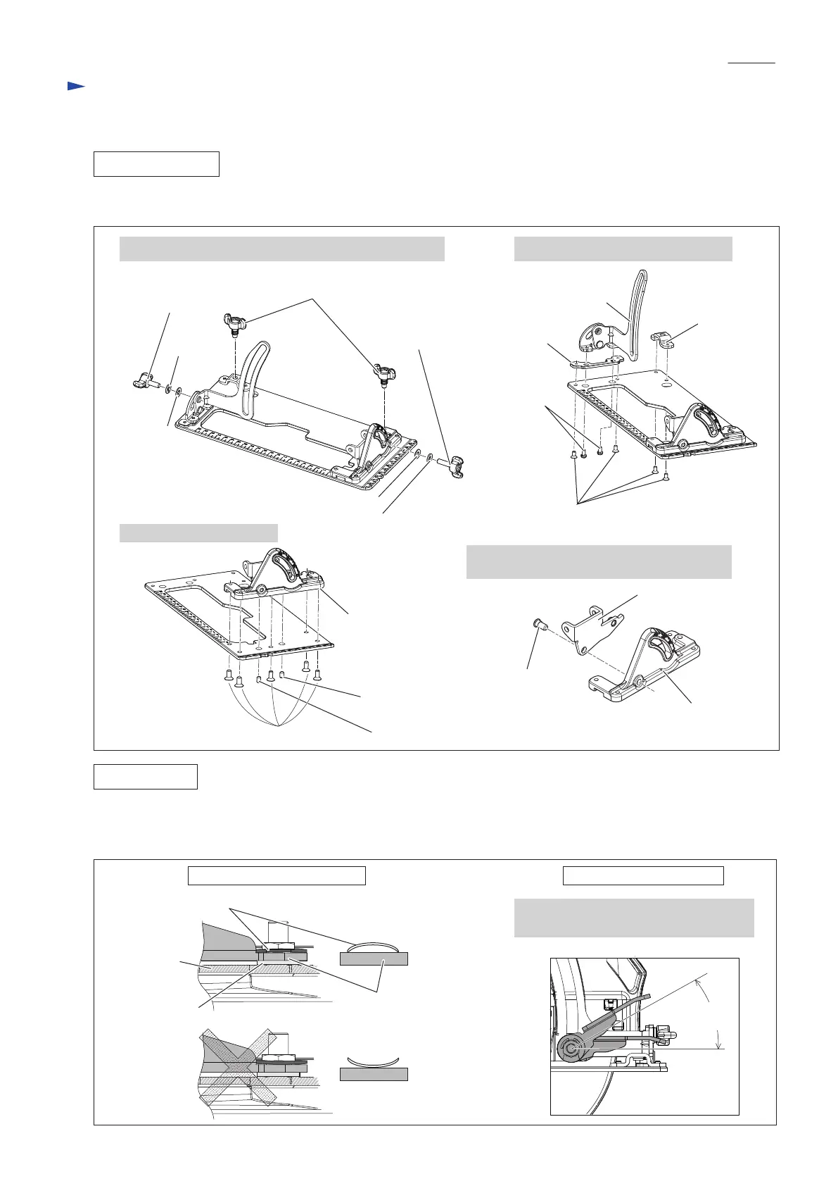
(4) Disassemble the components of Base. See Fig. 5.
1. Remove the following screws and washers from Base. 2. Remove Depth guide and Bracket.
3. Remove Angular plate.
4. Pull out 6-7 Shoulder pin, and then remove
Angular guide from Angular plate.
M6x12 Thumb screw
M6x16
Thumb screw
Spring
washer 6
Spring washer 6
Flat
washer 6
M6x21
Thumb screw
M4x8 Pan
head screw
( 2 pcs.)
Plate
Bracket
M4x8 Countersunk
head screw (4 pcs.)
Angular plate
Flat washer 6
Depth guide
M5X8 Hex socket set screw (for fixing 6-7 Shoulder pin)
M5x8 Hex socket
set screw
M5x12 Countersunk head screw (5 pcs.)
Assemble by reversing the disassembly procedure. Refer to Figs. 5, 4, 3 and 2.
Note: Bow stop ring E-12 and Lever plate in Depth guide section have to be assembled as drawn in Fig. 6.
6-7 Shoulder pin
Angular guide
Angular plate
Fig. 5
Fig. 6
ASSEMBLING
Lever plate
30° or less
Setting of Bow stop ring E-12
Depth guide
Flat washer 8
Right direction
Bow stop ring E-12
Wrong direction
Assembling of Lever plate
The angle of Lever plate has to be placed
between 0° to 30°.
P 5/ 11
Repair
 Loading...