Do you have a question about the Makita KP0800 and is the answer not in the manual?
Describes the intended purpose of the tool for planing wood.
Details power connection requirements and double insulation feature.
Specifies typical A-weighted noise levels and advises ear protection.
Details declared vibration emission values and safety precautions.
Manufacturer's declaration of compliance with European directives.
Ensures a clean, well-lit work area and keeps others away.
Covers plug matching, avoiding body contact with grounded surfaces, and weather protection.
Emphasizes staying alert, using PPE, and preventing unintentional starting.
Guidelines on correct tool usage, maintenance, and avoiding hazards.
Safety warnings specific to operating the planer, like securing workpieces.
Explains how to adjust cutting depth and operate the switch mechanism.
Instructions and cautions for blade replacement and tightening.
Detailed steps for installing standard planer blades with alignment.
Instructions for fitting mini planer blades and ensuring proper alignment.
Guidance on setting blades parallel to the rear base for optimal finish.
Instructions for connecting and using the dust bag accessory.
Describes how to hold and move the planer for effective wood planing.
Instructions for making stepped cuts using the edge fence.
Guides for attaching vacuum cleaner and elbow for chip management.
How to perform chamfering cuts using the 'V' groove on the front base.
Instructions for sharpening conventional blades using a sharpening holder.
Procedure for sharpening multiple blades simultaneously using a holder.
Steps for checking and replacing worn carbon brushes.
Lists recommended accessories and warns against using others.
Provides a comprehensive list of optional accessories for the planer.
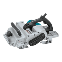
This document describes the Makita KP0800 Planer, a power tool designed for planing wood. It emphasizes safety, proper usage, and maintenance to ensure optimal performance and user safety.
The Makita KP0800 Planer is a double-insulated power tool used for planing wood. It features a rotating cutter drum with blades that remove material from the workpiece surface. The depth of cut can be adjusted using a knob on the front of the tool, allowing for precise material removal. The tool is equipped with a switch trigger for operation, which can be locked in the "ON" position for continuous use, enhancing operator comfort during extended tasks. A lock-off button is provided to prevent accidental starting, ensuring safety. The planer also includes a foot that raises the tool's rear base after a cutting operation, preventing damage to the blades.
To operate the planer, the user first adjusts the depth of cut by turning the knob until the pointer indicates the desired depth. Before starting, it is crucial to ensure the switch trigger functions properly and returns to the "OFF" position when released. For tools with a lock button, the switch can be pulled and then the lock button engaged for continuous operation; to stop, the trigger is pulled fully and then released. For tools with a lock-off button, the button must be depressed before pulling the switch trigger to start the tool.
When planing, the tool should be held firmly with one hand on the knob and the other on the switch handle. The front base of the tool is rested flat on the workpiece surface without the blades making contact. After switching on and allowing the blades to reach full speed, the tool is moved gently forward. Pressure should be applied to the front of the tool at the start of planing and to the back at the end. For rough cutting, a deeper cut can be used, while for a finer finish, the depth of cut should be reduced, and the tool advanced more slowly.
The planer can also be used for shiplapping (rabbeting) to create stepped cuts. This requires the use of an edge fence (guide rule), which is an accessory. A cutting line is drawn on the workpiece, and the edge fence is inserted into a hole in the front of the tool, aligning the blade edge with the cutting line. The fence is then adjusted to contact the side of the workpiece and secured. When planing, the tool is moved with the edge fence flush against the workpiece side to ensure even planing. The maximum shiplapping depth is 9 mm.
Chamfering cuts can be made by aligning the "V" groove in the front base with the edge of the workpiece and planing it. For dust collection, a dust bag (accessory) can be attached to the nozzle. The nozzle is tapered, and the bag should be pushed on firmly to prevent it from detaching during operation. Alternatively, a Makita vacuum cleaner can be connected for more efficient and cleaner operations. An optional elbow accessory can be used to change the chip discharge direction.
Regular maintenance is essential for the planer's safety and performance. Before any inspection or maintenance, the tool must be switched off and unplugged.
The planer blades must be kept sharp for optimal performance. For conventional planer blades, a sharpening holder (optional accessory) can be used to remove nicks and produce a fine edge. To remove blades, the installation bolts on the drum are unscrewed with a socket wrench, and the drum cover is removed. Before installing new blades, the drum surfaces and drum cover must be thoroughly cleaned of chips or foreign matter. Blades of the same dimensions and weight must be used to prevent drum oscillation/vibration and ensure uniform cutting. The blade is placed on the gauge base so its edge is perfectly flush with the inside edge of the gauge plate. The adjusting plate is then pressed flush with the back side of the gauge base, and two screws are tightened. The heel of the adjusting plate is slipped into the drum groove, and the drum cover is fitted. The installation bolts are then tightened evenly and alternately with the socket wrench.
For mini planer blades, the adjusting plate is loosely attached to the set plate with pan head screws, and the blade is set on the gauge base so its cutting edge is flush with the inside flank of the gauge plate. The adjusting plate/set plate is then set on the gauge base, ensuring the planer blade locating lugs rest in the mini planer blade groove. The heel of the adjusting plate is pressed flush with the back side of the gauge base, and the pan head screws are tightened. The blade's alignment must be carefully checked to ensure uniform cutting. The heel of the adjusting plate is slipped into the drum groove, and the drum cover is set over the adjusting plate/set plate. Three hex flange head bolts are screwed in, leaving a gap to slide the mini planer blade into position, which will be guided by the locating lugs on the set plate. The blade's lengthwise adjustment may be needed to ensure the blade ends are clear and equidistant from the housing. The hex flange head bolts are then tightened.
It is critical that the blade is mounted absolutely level and parallel to the rear base surface for a smooth and even planing surface. Improper settings can lead to nicks or gouging in the workpiece.
Carbon brushes should be checked regularly and replaced when they wear down to the limit mark. Both carbon brushes should be replaced simultaneously with identical brushes. To replace them, a screwdriver is used to remove the brush holder caps, the worn brushes are taken out, and new ones are inserted, securing the caps.
For all repairs, maintenance, or adjustments, Makita Authorized Service Centers should be used, ensuring only Makita replacement parts are utilized to maintain product safety and reliability. Handles should be kept dry, clean, and free from oil and grease.
| Idle speed | 17000 RPM |
|---|---|
| Sound power level | 100 dB |
| Planning width (max) | 82 mm |
| Sound pressure level | 89 dB |
| Input power | 620 W |
| Cable length | 2.5 m |
| Power source | AC |
| Chip thickness (max) | 2.5 mm |
| Product color | Black, Blue, Silver |
| Depth | 285 mm |
|---|---|
| Width | 158 mm |
| Weight | 2600 g |