Do you have a question about the Makita KP0810 and is the answer not in the manual?
Explains how to adjust the cutting depth using the knob and pointer.
Describes how to operate the switch trigger and lock-off button.
Step-by-step guide for safely removing and installing planer blades.
Details standard and mini planer blade installation and alignment.
Guidance on setting blades for a proper and even planing surface.
Instructions for holding the tool and performing planing.
Instructions for sharpening standard planer blades using a holder.
Procedure for checking and replacing worn carbon brushes.
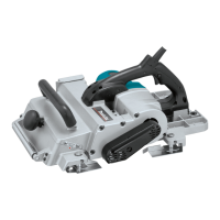
The Makita Power Planer, models KP0810 and KP0810C, is a double-insulated power tool designed for planing wood. For your personal safety, it is crucial to read and understand the instruction manual before using this tool and to save these instructions for future reference.
The planer features a knob and pointer system for adjusting the depth of cut. By simply turning the knob on the front of the tool, the pointer can be aligned with the desired depth of cut.
The tool is equipped with a switch trigger for operation. For models with a lock button, pulling the switch trigger starts the tool, and releasing it stops it. For continuous operation, the switch trigger can be pulled and then the lock button pushed in from either side. To stop the tool from a locked position, pull the switch trigger fully and then release it. For models with a lock-off button, a lock-off button is provided to prevent accidental starting. To start the tool, depress the lock-off button from either side and pull the switch trigger. Releasing the switch trigger stops the tool.
Model KP0810C includes electronic functions for enhanced ease of operation. These include constant speed control, which maintains a consistent rotating speed even under load, ensuring a fine finish. The soft-start feature minimizes start-up shock, allowing the tool to start smoothly.
A foot mechanism is integrated into the design. After a cutting operation, raising the back side of the tool causes a foot to extend, coming under the level of the rear base. This prevents the tool blades from being damaged when the tool is set down.
The chip discharge direction can be changed to the right or left. To adjust, pull out the stopper, turn it slightly backward, and fit it into one of the two openings on the opposite side of the chip discharge, ensuring the recessed part fits into the protrusion. An optional dust bag can be attached to the chip discharge opening to collect chips. The opening is tapered, so the dust bag should be pushed on firmly to prevent it from detaching during operation. When the dust bag is about half full, it should be removed, emptied, and tapped lightly to dislodge any adhering particles. An optional elbow accessory can also be used to change the chip discharge direction for cleaner work; it simply slips onto the opening and can be pulled off to remove.
The planer can be used for shiplapping (rabbeting) and chamfering. For shiplapping, an edge fence (guide rule) is used to make stepped cuts, and a depth guide (accessory) helps adjust the shiplapping depth. For chamfering, the front base of the tool has three "V" grooves (for small, medium, and great amounts of chamfering). Aligning one of these grooves with the workpiece edge allows for chamfering. An optional chamfering rule can be installed on the front base to provide more tool stability during shiplapping or extensive chamfering.
Before plugging in the tool, always ensure the switch trigger actuates properly and returns to the "OFF" position when released. When performing any adjustments or checking functions, the tool must be switched off and unplugged.
For planing operations, hold the tool firmly with one hand on the knob and the other on the switch handle. Begin by resting the tool's front base flat on the workpiece surface, ensuring the blades are not making contact. Switch on the tool and wait for the blades to reach full speed before gently moving the tool forward. Apply pressure on the front of the tool at the start of planing and at the back at the end. Incline the workpiece in a stationary fashion for easier planing, allowing for a slight downhill movement. The speed and depth of cut influence the finish; a greater depth of cut can be used for rough cutting, while a reduced depth and slower advance yield a good finish. The power planer is designed to cut at a speed that prevents jamming by chips.
For shiplapping, draw a cutting line on the workpiece, insert the edge fence into the hole in the front of the tool, and align the blade edge with the cutting line. Move the tool with the edge fence flush with the side of the workpiece to ensure even planing. For optimal shiplapping, the blade edge should protrude slightly (0.2 mm - 0.4 mm) outside. The edge fence can be extended by attaching an extra piece of wood using the provided holes, or an extension guide (optional accessory).
To install the chamfering rule, remove two screws on both sides of the front of the tool, set the depth of cut to 4 mm, and then secure the rule to the front base with the screws. When performing significant chamfering, position the chamfering rule's edge to contact the workpiece and make multiple passes.
For clean planing operations, a Makita vacuum cleaner can be connected to the chip discharge opening. This enhances efficiency and cleanliness.
Regular maintenance is essential for product safety and reliability. Always ensure the tool is switched off and unplugged before performing any inspection or maintenance.
Blade Installation and Removal: When removing blades, unscrew the installation bolts with the socket wrench. The drum cover will come off with the blades. For installation, clean all chips or foreign matter from the drum and blades. Use blades of the same dimensions and weight to avoid drum oscillation, poor planing, and tool breakdown. Place the blade on the gauge base so its cutting edge is perfectly flush with the inside edge of the gauge plate. Place the adjusting plate on the blade, press the heel of the adjusting plate flush with the back side of the gauge base, and tighten two screws on the adjusting plate. Then slip the heel of the adjusting plate into the drum groove, fit the drum cover, and tighten all installation bolts evenly and alternately with the socket wrench. Handle blades very carefully, using gloves or rags for protection. Only use the Makita wrench provided for installation and removal to prevent overtightening or insufficient tightening.
For mini planer blades, the process is similar. Loosely attach the adjusting plate to the set plate with pan head screws, and set the mini planer blade on the gauge base so its cutting edge is perfectly flush with the inside flank of the gauge plate. Ensure the planer blade locating lugs sit in the blade groove and the heel of the adjusting plate is flush with the back side of the gauge base. Slip the heel of the adjusting plate into the drum groove, set the drum cover over the adjusting plate/set plate, and screw in the three hex flange head bolts, leaving a gap to slide the mini planer blade into position. The blade's lengthwise adjustment needs to be manual, ensuring it is equidistant from the housing and metal bracket. Tighten the hex flange head bolts and rotate the drum to check clearances.
Blade Setting: Proper blade setting is crucial for a smooth and even planing surface. The cutting edge must be absolutely level and parallel to the rear base surface. Incorrect settings can lead to nicks, gouging at the start, or gouging at the end of the workpiece.
Sharpening (for standard blades only): Keep blades sharp for optimal performance. Use the sharpening holder to remove nicks and produce a fine edge. Loosen the two wing nuts on the holder, insert the blades (A) and (B) so they contact sides (C) and (D), then tighten the wing nuts. Immerse a dressing stone in water for 2-3 minutes before sharpening. Hold the holder so both blades contact the dressing stone for simultaneous sharpening at the same angle.
Carbon Brush Replacement: Regularly remove and check the carbon brushes. Replace them when they wear down to the limit mark. Keep the carbon brushes clean and free to slip in their holders. Both carbon brushes should be replaced at the same time, using only identical carbon brushes. Use a screwdriver to remove the rear cover, take out the worn brushes, insert new ones, and secure the rear cover.
All repairs, maintenance, or adjustments should be performed by Makita Authorized Service Centers, always using Makita replacement parts, to maintain product safety and reliability.
| Input power | 850 W |
|---|---|
| Power source | AC |
| Planning width (max) | 82 mm |
| Chip thickness (max) | - mm |
| Soft grip | Yes |
| Product color | Black, Blue |
| Depth | 290 mm |
|---|---|
| Width | 168 mm |
| Height | 176 mm |
| Weight | 3300 g |