Do you have a question about the Makita 1900B and is the answer not in the manual?
Instructions for removing and installing planer blades on the drum.
Guidance on setting planer blades correctly for optimal planing results.
How to adjust the cutting depth using the tool's knob.
Explanation of how to operate the power switch and lock-off button.
Steps and tips for performing the planing operation effectively.
Procedure for replacing worn carbon brushes on the tool.
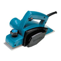
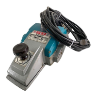
This document provides an operating manual for the Makita Power Planer models 1900B, N1900B, and 1902. It covers general safety instructions, detailed operating procedures, and maintenance guidelines to ensure safe and effective use of the tool.
The Makita Power Planer is an electric tool designed for planing wood surfaces. Its primary function is to smooth and level wood, as well as to create stepped cuts (shiplapping) and chamfers. The planer operates by means of rotating blades that remove thin layers of wood from the workpiece.
The tool is double-insulated, making it safe for use with single-phase AC power supplies and from sockets without an earth wire, in accordance with European Standard.
To operate the planer, first ensure it is connected to a power supply of the correct voltage. The tool should be held firmly, and hands should be kept away from rotating parts. Before using the tool on a workpiece, allow it to run for a while to check for any vibration or wobbling that might indicate poor installation or an unbalanced blade. Always wait until the blades attain full speed before cutting.
The depth of cut can be easily adjusted by turning the knob located on the front of the tool. This allows for precise control over the amount of material removed during planing. For rough cutting, a greater depth of cut can be used, while for a finer finish, the depth of cut should be reduced, and the tool advanced more slowly.
The planer may come with different switch configurations:
Always check that the switch trigger actuates properly and returns to the "OFF" position when released before plugging in the tool.
Begin by resting the tool's front base flat on the workpiece surface, ensuring the blades do not make contact. Switch on the tool and wait for the blades to reach full speed. Then, gently move the tool forward. Apply pressure on the front of the tool at the start of planing and at the back at the end of planing. Planing can be made easier by inclining the workpiece in a stationary fashion, allowing for planing somewhat downhill. The tool is designed to cut at a speed that prevents jamming by chips.
To create a stepped cut (shiplapping), use the edge fence. Draw a cutting line on the workpiece, insert the edge fence into the hole in the front of the tool, and align the blade edge with the cutting line. Adjust the edge fence until it contacts the side of the workpiece, then secure it by tightening the screw. An extra piece of wood can be attached to the fence for added length, or an extension guide can be used. When planing, move the tool with the edge fence flush with the side of the workpiece to ensure even planing. The maximum shiplapping depth is 9 mm.
To create a chamfered cut, align the "V" groove in the front base with the edge of the workpiece and plane it accordingly.
An optional nozzle assembly can be attached to minimize chip scatter and create a cleaner work area. To install, remove the chip cover on the tool body, slip on the nozzle assembly, fitting its pin into the rear cover hole, and fasten it in place with the chip cover screws.
CAUTION: Always ensure the tool is switched off and unplugged before performing any work on the tool.
For standard planer blades: To remove, unscrew the three installation bolts with a socket wrench. The drum cover will come off with the blades. To install, first clean any chips or foreign matter from the drum or blades. Use blades of the same dimensions and weight to prevent oscillation or vibration. Place the blade on the gauge base so its edge is perfectly flush with the inside edge of the gauge plate. Place the adjusting plate on the blade, press the heel of the adjusting plate flush with the back side of the gauge base, and tighten two screws on the adjusting plate. Slip the heel of the adjusting plate into the drum groove, fit the drum cover, and tighten the three installation bolts evenly and alternately with the socket wrench.
For mini planer blades: To remove, carefully clean the drum surfaces and drum cover. Unscrew the three installation bolts with a socket wrench; the drum cover comes off with the blades. To install, loosely attach the adjust plate to the set plate with pan head screws. Set the mini planer blade on the gauge base so its cutting edge is perfectly flush with the inside flank of the gauge plate. Set the adjusting plate/set plate on the gauge base so the planer blade locating lugs on the set plate rest in the mini planer blade groove. Press in the heel of the adjusting plate flush with the back side of the gauge base and tighten the pan head screws. Ensure the blade sits flush with the inside flank of the gauge plate, the planer blade locating lugs sit in the blade groove, and the heel of the adjusting plate is flush with the back side of the gauge base for uniform cutting. Slip the heel of the adjusting plate into the drum groove. Set the drum cover over the adjusting plate/set plate and screw in the three hex flange head bolts, leaving a gap between the drum and the set plate to slide the mini planer blade into position. The blade will be positioned by the planer blade locating lugs on the set plate. The blade's lengthwise adjustment needs to be manually positioned so that the blade ends are clear and equidistant from the housing on one side and the metal bracket on the other. Tighten the three hex flange head bolts with the provided socket wrench and hand rotate the drum to check clearances between the blade ends and the tool body. Finally, check the three hex flange head bolts for final tightness and repeat the process for the other blade. Always tighten the blade installation bolts carefully and securely.
Keep blades sharp for optimal performance. Use the sharpening holder to remove nicks and create a fine edge. First, loosen the two wing nuts on the holder and insert blades (A) and (B) so they contact sides (C) and (D). Then tighten the wing nuts. Immerse the dressing stone in water for 2 or 3 minutes before sharpening. Hold the holder so both blades contact the dressing stone for simultaneous sharpening at the same angle.
Regularly remove and check the carbon brushes. Replace them when they wear down to the limit mark. Keep the carbon brushes clean and free to slip in their holders. Both carbon brushes should be replaced simultaneously with identical carbon brushes. Use a screwdriver to remove the chip cover, then use a screwdriver to remove the brush holder caps. Take out the worn carbon brushes, insert the new ones, and secure the brush holder caps.
To maintain product safety and reliability, any repairs, maintenance, or adjustments should be performed by Makita Authorized or Factory Service Centres, using only Makita replacement parts. Periodically inspect the tool cord and extension cords for damage and have them repaired or replaced if necessary. Keep handles dry, clean, and free from oil and grease.
| Power Input | 500W |
|---|---|
| No Load Speed | 16, 000 RPM |
| Maximum Cutting Depth | 1mm |
| Cord Length | 2.5m |
| Planing Width | 82mm |
| Planing Depth | 1mm |