Do you have a question about the Makita 1923B and is the answer not in the manual?
How to adjust the cutting depth using the knob on the front of the tool.
Instructions on how to start, stop, and lock the tool's trigger switch.
Guidance on how to hold and move the planer for effective cutting.
Instructions for making a V-groove cut using the front base.
How to attach and use the nozzle assembly for cleaner chip collection.
Procedure for checking and replacing worn carbon brushes.
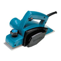
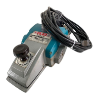
This document is an instruction manual for the Makita Power Planer, Model 1923B, an 82 mm (3-1/4") tool featuring double insulation. It provides essential information for safe operation, maintenance, and optimal use of the planer.
The Makita Power Planer Model 1923B is designed for planing wood surfaces, making stepped cuts (shiplapping), and chamfering edges. It utilizes rotating blades to remove material from a workpiece, allowing for smooth finishes or specific woodworking profiles. The tool is hand-held and intended for use in various woodworking applications, from rough cutting to fine finishing. Its design emphasizes user safety and efficient material removal.
The manual emphasizes a comprehensive set of safety precautions for all electric tools, including keeping the work area clean and well-lit, avoiding damp or wet locations, and not exposing the tool to rain or flammable substances. It stresses the importance of keeping children and visitors away from the work area and storing idle tools securely. Users are advised to use the right tool for the job, dress properly (avoiding loose clothing and jewelry), wear safety glasses and dust masks, and secure the workpiece with clamps or a vise. Maintaining tools with care, inspecting cords, and disconnecting tools before servicing or changing accessories are also highlighted. A critical warning is given regarding voltage, ensuring that the power source matches the tool's nameplate specifications to prevent serious injury or damage.
Users must avoid leaving rags or cords around the work area and inspect workpieces for nails before operation. Blades should be handled carefully, and installation bolts must be securely tightened. The tool should be held firmly with both hands, and hands kept away from rotating parts. Before actual use, the planer should be run for a while to check for vibration or wobbling, which could indicate improper blade installation. The blade must not contact the workpiece before the switch is turned on, and full speed should be attained before cutting. Users should maintain a distance of at least 200 mm (8") from the tool at all times. The tool must be switched off, and blades allowed to stop completely before any adjustments. Sticking fingers into the chip chute is prohibited, and jammed chutes should be cleared with a stick. The planer should only be operated when hand-held and switched off, with the front base up on a wooden block, when left unattended. It is crucial to change both blades or drum covers simultaneously to prevent imbalance, vibration, and reduced tool life.
To remove blades, the three installation bolts are unscrewed with a socket wrench, allowing the drum cover and blades to come off. For installation, all chips and foreign matter must be cleaned from the drum and blades. It is essential to use blades of the same dimensions and weight to prevent vibration and poor planing. The blade is placed on the gauge base, ensuring its edge is flush with the inside edge of the gauge plate. The adjusting plate is then placed on the blade, its heel pressed flush with the back side of the gauge base, and two screws tightened. The adjusting plate's heel is slipped into the drum groove, followed by fitting the drum cover. The three installation bolts are then tightened evenly and alternately with the socket wrench.
This process involves removing existing blades, cleaning drum surfaces and the drum cover. The adjust plate is loosely attached to the set plate with pan head screws, and the mini planer blade is set on the gauge base so its cutting edge is flush with the inside flank of the gauge plate. The adjust plate/set plate assembly is then placed on the gauge base, ensuring the planer blade locating lugs rest in the mini planer blade groove. The heel of the adjust plate is pressed flush with the back side of the gauge base, and pan head screws are tightened. Careful alignment is crucial for uniform cutting. The heel of the adjust plate is slipped into the drum groove. The drum cover is set over the adjust plate/set plate, and three hex flange head bolts are screwed in, leaving a gap to slide the mini planer blade into position, guided by the locating lugs. Lengthwise adjustment is manual, ensuring blade ends are clear and equidistant from the housing and metal bracket. The three hex flange head bolts are tightened with a socket wrench, and the drum is rotated to check clearances. Final tightness of the bolts is verified. These steps are repeated for the other blade.
For shiplapping, the blade edge should protrude slightly (0.3 mm – 0.6 mm: 1/64″ – 1/32″) to prevent nicks and poor results. Blade installation bolts must be tightened securely, as loose bolts are dangerous. The planing surface will be rough and uneven if blades are not set properly and securely. Blades must be mounted so the cutting edge is absolutely level and parallel to the rear base surface. The manual provides examples of proper and improper settings, illustrating how nicks or gouging can result from blades not being parallel or protruding too much/too little.
The depth of cut is adjusted by turning the knob on the front of the tool.
To start the tool, the trigger is pulled. Releasing it stops the tool. For continuous operation, the trigger is pulled, and the lock button is pushed in. To stop from the locked position, the trigger is pulled fully and then released. A caution advises checking that the trigger switch actuates properly and returns to the "OFF" position when released before plugging in the tool.
The tool's front base is rested flat on the workpiece surface without blade contact. The tool is switched on, and blades are allowed to reach full speed. It is then moved gently forward, applying pressure on the front at the start of planing and at the back at the end. Planing is easier if the workpiece is inclined stationary, allowing for downhill planing. The speed and depth of cut determine the finish quality. The power planer maintains a cutting speed that prevents chip jamming. For rough cutting, depth of cut can be increased; for a good finish, depth of cut should be reduced, and the tool advanced more slowly.
To make a stepped cut, the edge fence is used. A cutting line is drawn on the workpiece. The edge fence is inserted into the hole in the front of the tool and aligned with the blade edge and cutting line. The edge fence is adjusted to contact the side of the workpiece and secured by tightening a screw. An extra piece of wood can be attached to the fence for added length, using provided holes for this purpose or for an extension guide (optional accessory). When planing, the tool should be moved with the edge fence flush with the workpiece side to avoid uneven planing. The maximum shiplapping depth is 23 mm (15/16").
To make a chamfer cut, the "V" groove in the front base is aligned with the edge of the workpiece, and the tool is planed as shown in the figure.
The special nozzle assembly minimizes chip scatter, contributing to a cleaner work area. It is attached after removing the chip cover on the tool body. The pin on the assembly fits into the rear cover hole, and chip cover screws fasten it in place.
Blades should always be kept sharp for optimal performance. A sharpening holder is used to remove nicks and produce a fine edge. First, the two wing nuts on the holder are loosened, and blades (A) and (B) are inserted to contact sides (C) and (D). The wing nuts are then tightened. The dressing stone should be immersed in water for 2 or 3 minutes before sharpening. The holder is held so both blades contact the dressing stone for simultaneous sharpening at the same angle.
A caution advises ensuring the tool is switched off and unplugged before any inspection or maintenance.
Carbon brushes should be removed and checked regularly. They must be replaced when worn down to the limit mark. Brushes should be kept clean and free to slip in their holders. Both carbon brushes must be replaced at the same time, using only Makita carbon brushes. A screwdriver is used to remove the chip cover. Then, a screwdriver is used to remove the brush holder caps, worn carbon brushes are taken out, new ones inserted, and brush holder caps secured.
To maintain product safety and reliability, all repairs, maintenance, or adjustments should be performed by Makita Authorized or Factory Service Centers, always using genuine Makita replacement parts.
The manual lists various accessories recommended for use with the Makita Power Planer Model 1923B. These include:
The manual cautions that using any other accessories or attachments might pose a risk of injury and that accessories should be used only in the proper and intended manner.