Chapter 2 Hardware features
Page 2-4 MAN 0385
amber if the dispersion unit is functioning correctly but its cell has not been
loaded into the optical bench. (i.e. the dispersion unit is at “standby”)
red if the dispersion unit detects an error. If an error message does not appear
on the screen, selecting Configure-Accessory displays the accessory control
dialogue which should show the error.
Rear panel
The rear panel contains all services and communication connectors for the disper-
sion unit. More details on the rear panel are given later in this chapter.
Cell holder
The Mastersizer 2000 system is designed so that more than one dispersion unit can
be connected at once. The cell holder provides a convenient storage location for the
flow cell if another dispersion unit is in use.
The cell holder reduces the build up of dust on the cell windows when not in use.
If the cell is not used for short periods (up to 24 hours), leave the cell and tank full
of clean dispersant so that the cell windows do not dry out, leaving smears or water
marks on the window surface.
If the push on connectors are to be removed, the cell may be stored wet by using
the syringe supplied to fill it with clean dispersant.
If the cell is not to be used for longer periods, remove and dry the cell windows;
the Essentials Manual has details. The cell holder houses the window removing
tool in its base.
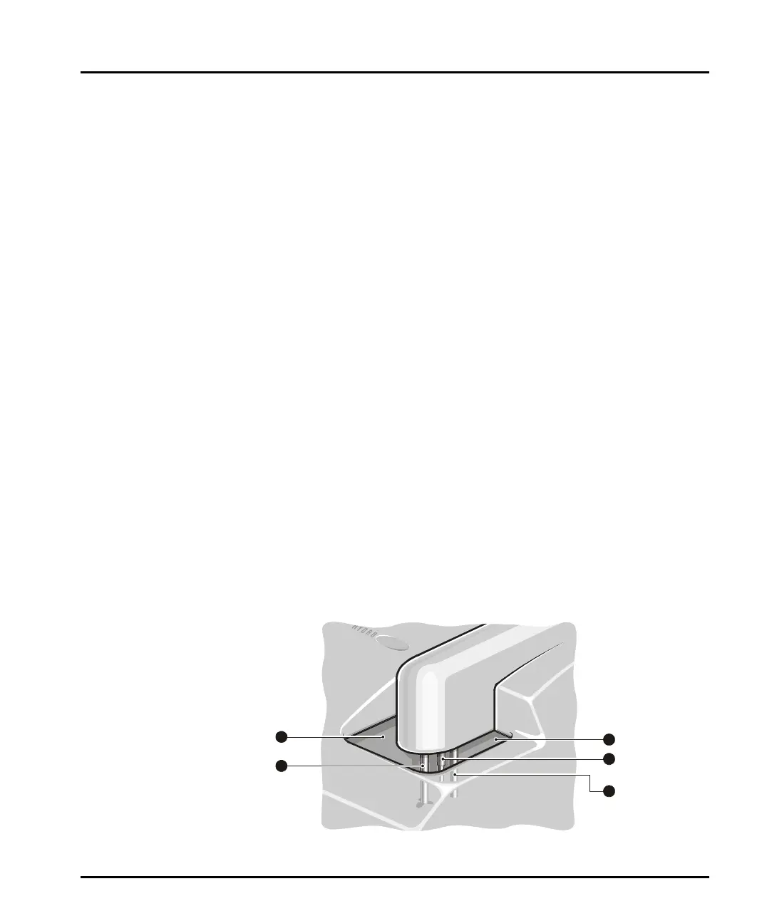
Tank area
As described above, the tank holds the sample and dispersant. The pump and stirrer
in the tank keep the sample in suspension and continually circulate the sample and
dispersant through the cell. This diagram identifies the features of the tank area:
ill 4914
1
3
4
5
3
2
1
MAN0385-1.0 Hydro 2000G-S.book Page 4 Friday, March 16, 2007 4:02 PM