Do you have a question about the Man E 0824 E 301 and is the answer not in the manual?
Essential safety measures for handling gaseous fuels, including operation, leaks, and fire.
Rules for preventing accidents and injuries to personnel during engine commissioning, starting, and operation.
Guidelines for safe practices during engine maintenance and care activities.
Safety protocols for performing checks, adjustments, and repair work on the engine.
Regulations and advice to prevent engine damage, premature wear, and environmental pollution.
Health precautions, safe handling practices, and proper disposal methods for used engine oil.
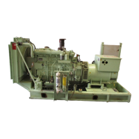
Diagrams identifying key components of the MAN E 0824 E 301 / 302 engine.
Diagrams identifying key components of the MAN E 0826 E 301 / 302 engine.
Steps for filling coolant and engine oil during initial setup.
Procedure for checking the engine oil level using the dipstick.
Setup, positioning, adjustment, and connection of the engine control unit.
Instructions for starting the engine with asynchronous and synchronous generators.
Procedures for monitoring system status and safely stopping the engine.
Procedures for draining engine oil, changing filters, and refilling with new oil.
Steps for draining coolant, adding new coolant, and bleeding the system.
Procedure for removing lime deposits and treating waste water from the cooling system.
Guidelines for fitting new spark plugs and recommended replacement intervals.
Information on air filter servicing and checks for the starter motor.
Requirements for anti-corrosion protection when engines are stored long-term.
Method for checking and adjusting engine ignition timing with a stroboscopic lamp.
Procedure to set the maximum engine speed limit for safety.
Steps for adjusting valve clearances, ensuring the engine is cold.
Detailed specifications for the MAN E 0824 E 301 / 302 industrial gas engine.
Data related to the ignition system, make, type, and spark plug gap.
Detailed specifications for the MAN E 0826 E 301 / 302 industrial gas engine.
Diagram showing input signal connections to the engine control unit.
Diagram illustrating output signal connections for the E 0824 E engine.
Diagram illustrating output signal connections for the E 0826 E engine.