Commissioning and operation
18
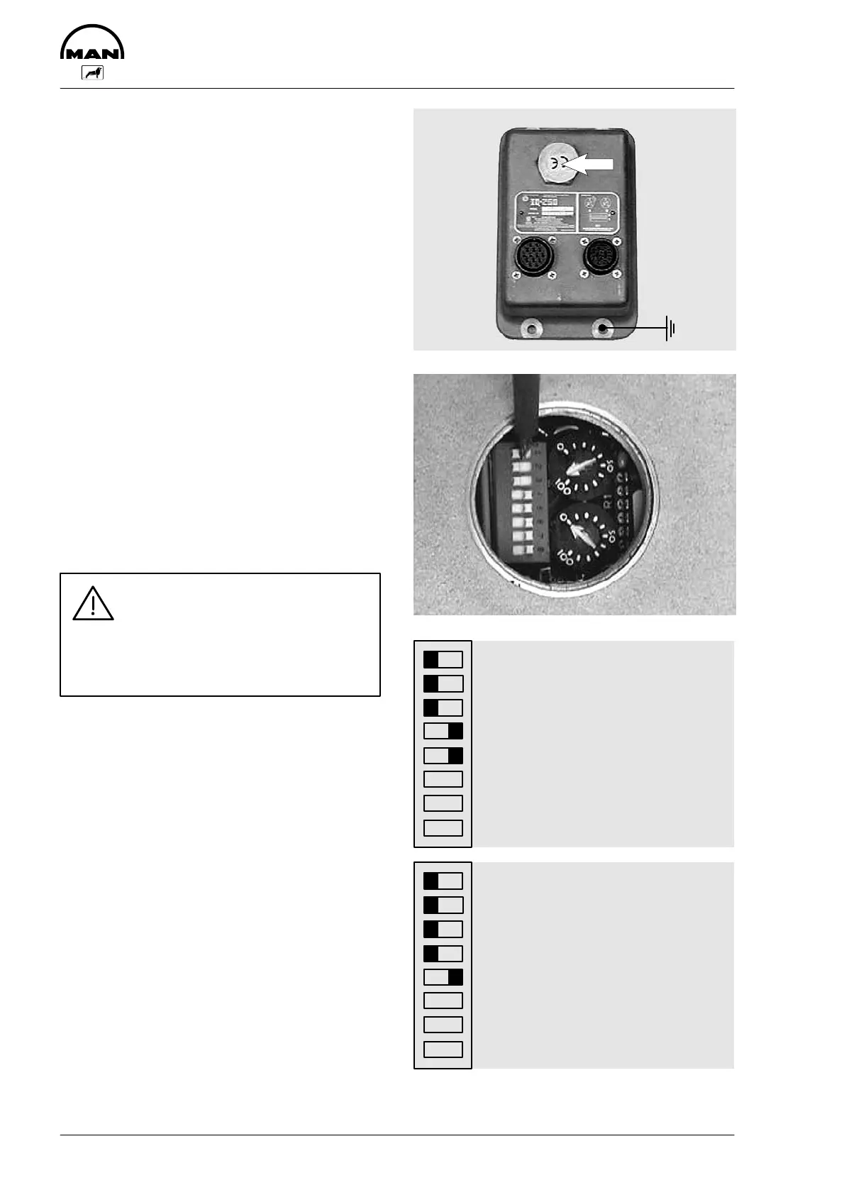
The control unit (option)
Purpose of the control unit
The control unit records the respective
crank angle of the engine at very short in-
tervals and calculates from these data the
time for triggering the ignition pulse for
each and every cylinder.
Positioning of the control unit
The control unit is arranged close to the
engine so that the following conditions are
met:
D Mounted on a stable support, with
vibration damping by rubber elements if
necessary
D Max. ambient temperature 70_C
D Earthing strip run from housing of con-
trol unit to the engine
Danger:
Disconnect battery before doing
any work on electric cables or
making adjustments to the con-
trol unit as described here!
Adjusting ignition sequence and tim-
ing
The same control unit is used for the
4-cylinder and the 6-cylinder engine.
The ignition sequence and timing must
therefore be set before the unit is used for
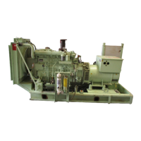
the first time. To do this, unscrew the
cover (see arrow in upper figure). You will
now see 2 potentiometers and a switch
panel with a total of 8 switches.
The first 5 switches are set to the posi-
tions shown on the right using a small
screwdriver.
Switches 6, 7 and 8 are not required.
1
2
3
4
5
6
7
8
Control unit setting for
the 4-cylinder
E 0824 E engine
1
2
3
4
5
6
7
8
Control unit setting for
the 6-cylinder
E 0826 E engine