Transmission of power by propshafts
34
Flywheels
Note:
To carry out an exact installation
inspection, request an installation drawing
showing detailed dimensions for the
flywheel or flywheel housing.
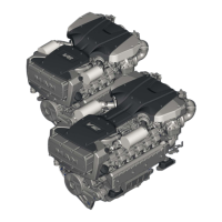
À Flywheel with I = 1.1 kgm
2
for the installation of
a highly resilient coupling
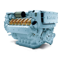
Á Flywheel with I = 1.9 kgm
2
for the installation of
a resilient coupling with flanged bearing
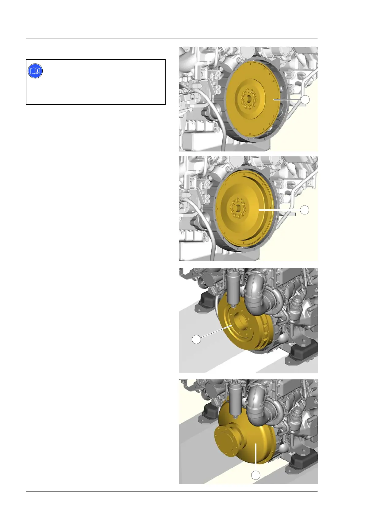
Highly resilient coupling
The highly resilient coupling  is installed at the
engine’s flywheel. The coupling can only be
installed if the engine is equipped with the
corresponding flywheel for propeller shaft
couplings À.
It allows permissible propeller shaft−working angles
ß
1
, ß
2
of 3°.
For interface dimensions see installation drawing.
Resilient coupling with flange bearing
The resilient coupling with flange bearing à is
installed on the engine at the factory. The coupling
can only be installed if the engine is equipped with
the corresponding flywheel Á.
It allows permissible propeller shaft−working angles
ß
1
, ß
2
of 9°.
For interface dimensions see installation drawing.
Weight: 128 kg
1
2
3
4
 Loading...