Combustion air system and charging
38
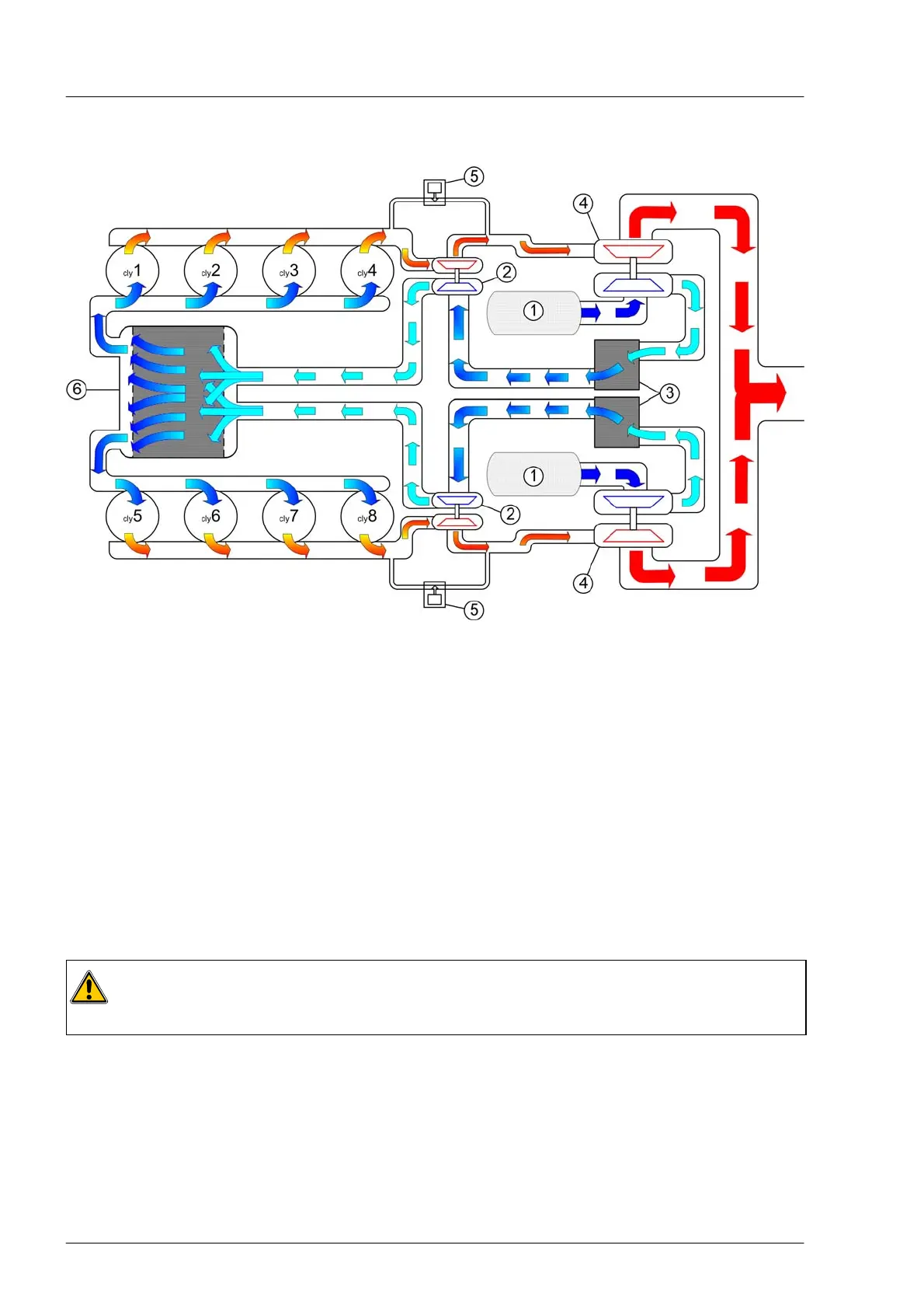
Diagram of the charging
À Air filter
Á Turbocharger, high compression stage
 Intercooler
à Turbocharger, low compression stage
Ä Boost pressure control valve
Å Charge air cooler
The diagram shows the combustion air ducting on the V8−1200. The design is identical for V12−1800.
There are two stages of turbocharging whereby the combustion air is cooled after each stage. Each
cylinder bank has one low compression stage turbocharger, one intercooler and one high compression
stage turbocharger.
After passing through the air filter, the combustion air is pre−compressed by the low compression stage
turbocharger and cooled by the intercoolers. The high compression stage turbocharger compresses the
combustion air to the final pressure. Before the air reaches the cylinders, the air is cooled in the charge air
cooler to a temperature of approx. 50°C. The waste gates limit the amount of combustion air flow and
prevents an overload of the engine.
Both the intercooler and the charge air cooler are supplied with sea water.
Caution:
The proper operation of the charge air cooler and the intercooler can only be ensured if sufficient
sea water is supplied, see chapter “Cooling system” page 45.
 Loading...