12
4.4 ADJUSTMENT OF LIMIT SWITCHES
1. Open the cover of the electrical enclosure.
WARNING
NEVER PLACE HANDS OR TOOLS INSIDE OPERATOR OR NEAR DRIVE MECHANISM UNLESS POWER IS OFF
Fi
ure 1
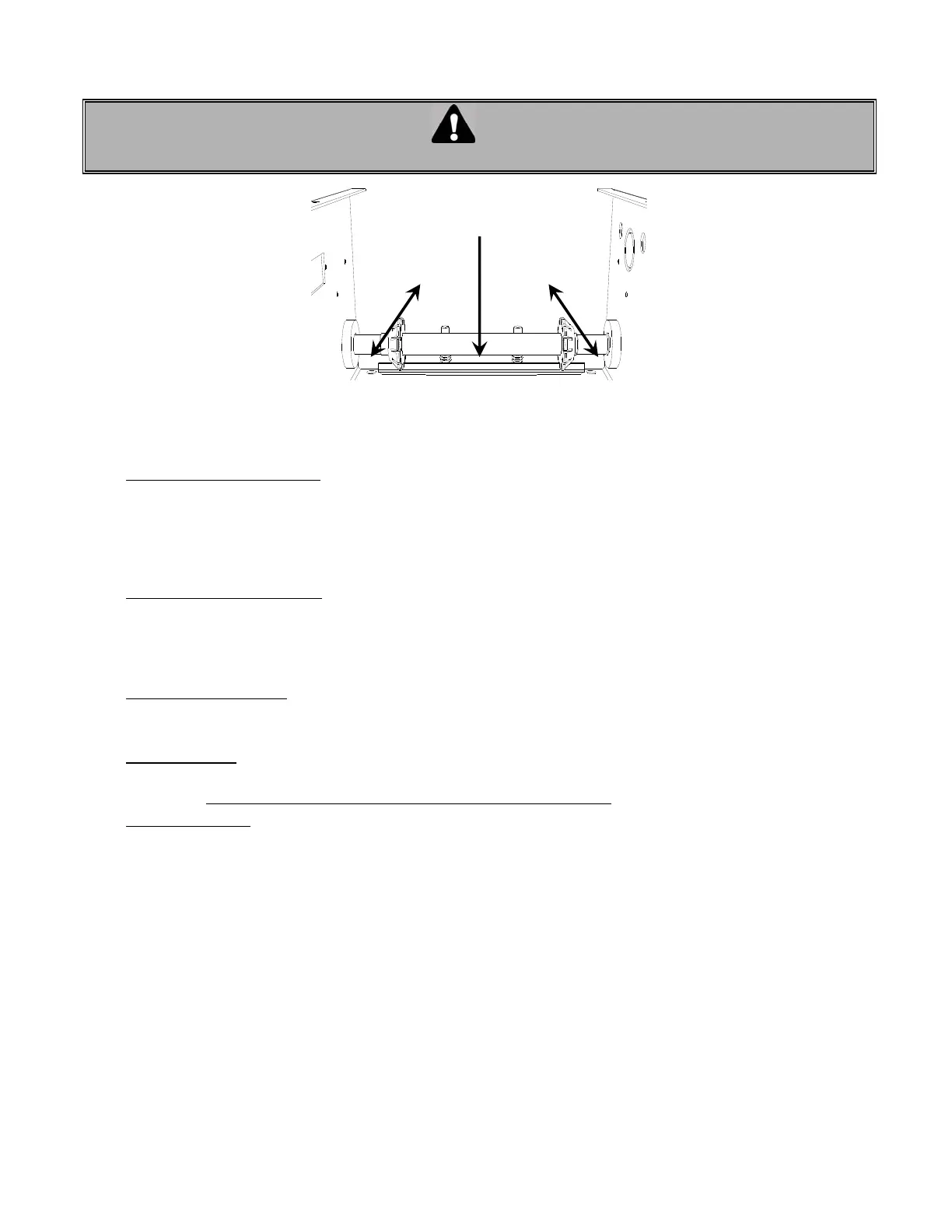
Adjusting the limit cams
Note: Turning the cam towards the center on the limit shaft increases door travel.
Turning the cam towards the limit switch decreases door travel.
• Open limit switch adjustment:
2. Manually raise the door to a nearly opened position or desired open position.
3. Depress the cams-retaining bracket from the Open side and rotate manually the Open cam (Figure 16)
until the cam activates the limit switches sufficiently so as to hear the switches click (2 clicks for hardwired
circuit. Only one click with ECB and check if the OPEN limit light is ON).
4. Release cam-retaining bracket and make sure that the bracket engages in the slots of both cams.
• Close limit switch adjustment:
5. Manually lower the door to a nearly to 6” above the ground.
6. Depress the cams-retaining bracket from the Close side and rotate manually the Close cam (Figure 16)
until the cam activates the Close limit switch sufficiently so as to hear the switch click (2 clicks for hardwired
circuit. Only one click with ECB and check if the CLOSE limit light is ON).
• Testing door electrically:
7. Upon completion of all wiring connections, use the wall push buttons (or on board buttons for ECB), to run
the door electrically and check if it is stopping properly to fully open and fully close positions.
• Fine adjustment:
If door is not opening or closing properly or if there is a gap between the door and floor, re-adjust the close
limit switch. Note: One (1) on cam is equal to about ½” on the door travel.
For close position:
Adjust one notch at a time until the close limit switch is properly adjusted and the door
stop smoothly on closed position.
8. Close the control box once the limit switches are adjusted.
4.5 MINIMUM SUGGESTED WIRE SIZE FOR CONTROL CIRCUIT
The control circuit operates at 24 VAC. Due to the resistance in the wire used to carry the control circuit voltage, it
is important to use the appropriate wire size with respect to the distance between the operator and the push-
button station.
Below is a chart (TABLE 2) indicating the minimum recommended wire size with respect to the total distance
between the operator and the push-button station. DO NOT exceed the maximum distance. If there are
several push-button stations in series you must ADD all these distances before selecting the appropriate wire
gauge for your operator.
If the wire gauge is not suitable for the distance, problems in operation will be encountered such as chattering
relays and contactor, premature wear of the contacts and possible tripping of the motor's thermal protection.
If a greater distance is required, a long distance interface module is suggested (consult factory).
When large gauge wire is used, a separate junction box will be needed for operator power connection (not
supplied).
Rotate cams to
desired position
Press down on
cam retaining plate to
rotate cams
Open Cam
(Open side)
Close Cam
(Close side)
 Loading...