23
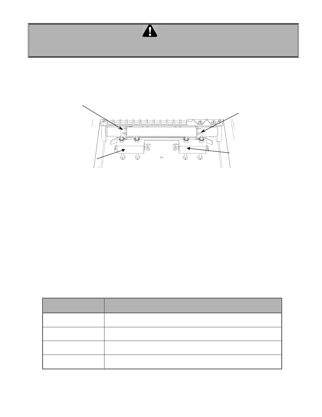
7.7 LIMIT SWITCHES
WARNING
TO AVOID THE DANGER OF POSSIBLE DAMAGE TO THE DOOR AND OPERATOR, TRAVELLING CAMS
MUST BE ADJUSTED TO THEIR APPROXIMATE POSITIONS BEFORE MANUALLY OPERATING THE
DOOR OR BEFORE APPLYING POWER TO THE OPERATOR.
Only 2 limit switches are used in operators built with an Electronic Control Board. One for the “Open” side
and one for the “Close” side. No advanced Open or Closed limit switches is used. The microprocessor with
the built-in logic replaces the advanced Open and Closed limit switches (Figure 18).
7.8 DESCRIPTION LIMIT SWITCHES
• The “Open” limit switch is the end of travel in the open position. Adjust the cam so that the door stops
in the open position at the desired location.
• The “Close” limit switch is the end in the close position. Adjust the cam so that the door stops in the
closed position at the desired position.
7.9 TROUBLE SHOOTING AN OPERATOR WITH ECB
Troubleshooting an operator with an ECB is easier since the LEDs provided on the circuit board help to bring
a better diagnostic while finding the faults.
Easy fix
Check the followings that may prevent the operator from starting
before coming to any conclusion
Check light status on
the ECB
Before starting any intervention, check the LEDs status and refer to the
page 17 for a proper diagnostic.
Check the operating
modes
Review the operating modes: B2, C2, D1, T or TS
Check the
programming
A wrong programming on Timer to Close or Mid Stop will stop the door to
an improper position.
Check the presence
of stop jumper
If the 3 test buttons are being used without the stop jumper between #8 &
#9, the operator will not respond to the 3 buttons command
Fi
ure 18 Limit switches
"Open" limit switch "Close" limit switch
‘’Open Position’’ cam
"Close Position" cam
 Loading...