16
Before installing power and control wiring, be sure to follow
all specifications described below. Failure to do so may damage
the operator.
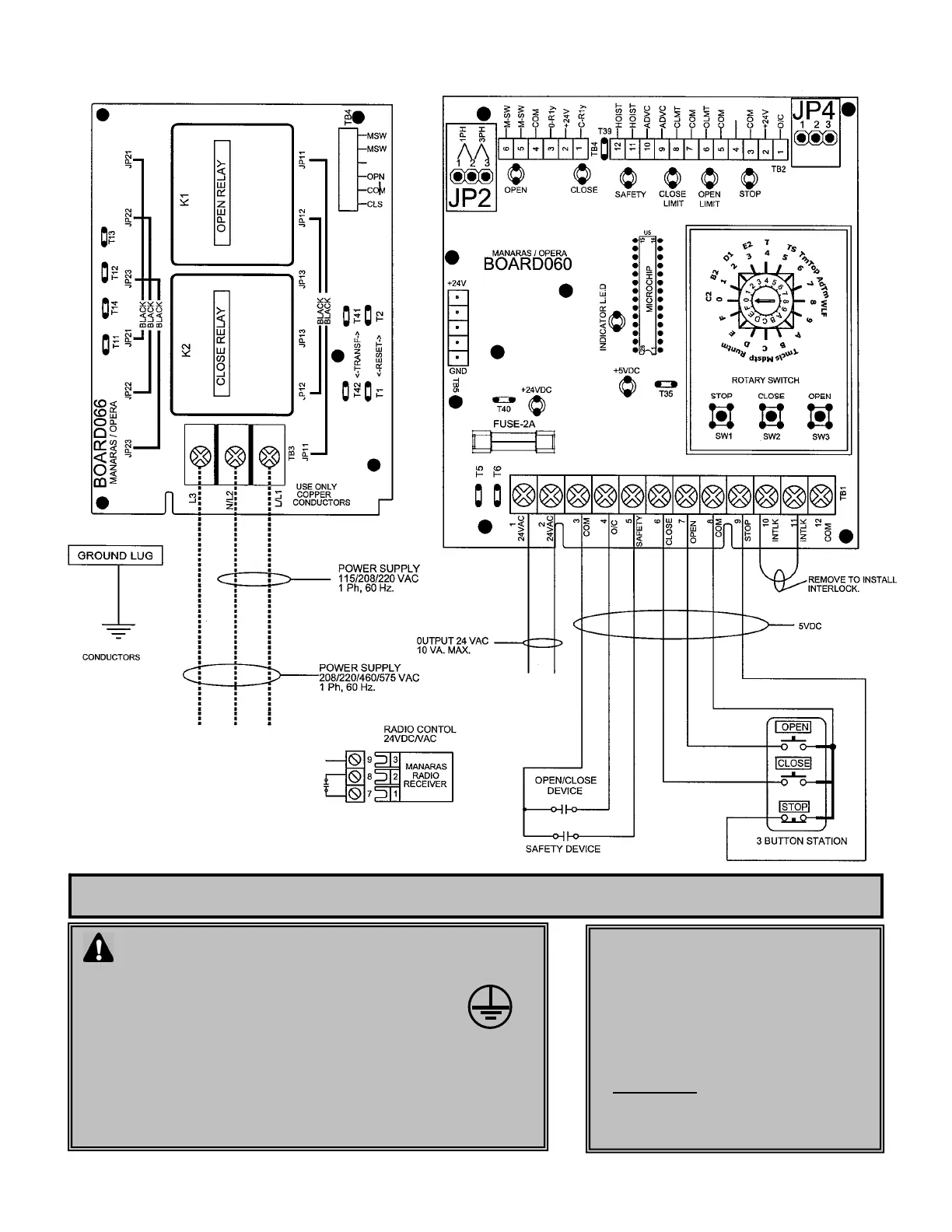
• The operator must be properly grounded and connected in
accordance to local electrical codes.
• Use different knockouts available on EACH side of the control box to
pass the power and control wiring through.
• Ensure maximum separation between power wiring and low
voltage control wirings in the control box.
• Please refer to next page for details.
• If a push button is not used, a jumper
must be placed between #8 & #9
***Under this condition a stop command is
not available to stop the door during its
travel.
• Please refer to Accessories Wiring
diagrams (TN005E) before connecting
any external accessories
• 2 Amp fuse is used to protect 24VDC
on electronic board and also the 24VAC
supply for auxiliary control devices
7.1 POWER AND CONTROL WIRING DIAGRAM
VERY IMPORTANT NOTES
 Loading...