28
8.2 Warning Light Sequence
8.3 Programming warning lights sequence (door should be in the closed position)
NOTE: Warning lights is functional only with Timer to Close
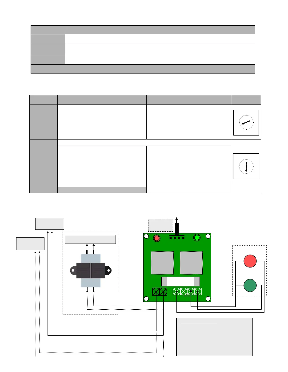
8.4 Connection of Red and Green warning lights
(If Warning Lights Module is sold separately)
Lights Operating sequence
Red
The light is solid red when the door is closing and opening. Light turns OFF once the door reaches
the fully open or fully closed position
Green
The green light is ON only when the door is fully open and stays ON during a preset time (programmed
by the Timer to Close)
Red
(flashing)
The red light starts flashing once the green light is OFF and when the door is about to close. This is to
warn the users that the door will close shortly. It stops flashing once the door start closing.
Warning lights sequence is operational from Mid-Point position in same way as from fully open
SETTING ACTIVATE DEACTIVATE
SELECT
SWITCH
TIMER TO
CLOSE
• Set select switch on “B”
• Press “Open” button to add 15 sec or
“Close” button to add 1 sec each time
(max. 4 minutes & 30 seconds)
• Set the select switch on 4 (T) or 5 (TS)
mode
• Set select switch on “B”
• Press “Stop” button the timer to close
is reset to 0 sec but still is activated.
• To deactivate the timer to close
completely set the switch on desired
position (0, 1, 2 or 3)
RED
LIGHTS
(Flashing
Time)
DEFAULT TIME SETTING 5 SEC
• Set select switch on “8”
• Press “Open” to add 1 sec each time to
a maximum of 15 sec.
• Press “Close” to deduct 1 sec each time
to a minimum of 0 sec.
• Press “Stop” to bring the flashing time
to 5 sec by default
• Set select switch on “8” and press
“Close” to bring the flashing time to 0
sec.
• Or set the select switch to desired
position (0, 1, 2 or 3)
Bring back select switch on T (4) or TS (5)
D
A
B
C
9
8
F
E
0
4
6
5
7
2
1
3
C
D
B
A
9
8
F
E
0
5
6
7
2
1
4
3
Traffic lights
For 115V AC lights only
(on 230/460/575V
operators)
Installation instructions:
• Use the four support posts supplied to fix the
light module
• Make sure that the module is properly
secured inside the control box.
• Refer to the programming instructions to set
the light sequence.
RED
J2
J4
RED
GREEN
Fuse
4 Amps
RELAY 1
RELAY 2
TO #TB5 of
BOARD060
RED COM GRN
L N
Red
Green
Warnin
li
hts Module
230/460/575V
Transformer
100VAC
115V AC
To L&N on TB3 of BOARD066
For 115V AC lights on 115V operators only
To L&N on TB3
For 24V AC lights only (all voltage operators)
To 1&2 on TB1
of BOARD060
J1
 Loading...