19
7.2 ELECTRONIC CONTROL BOARD
LED MONITORING STATUS
LED’s on the ECB help will wiring and making troubleshooting diagnoses. Every LED states the actual position of
the door. The board has a non-volatile memory and all the LED return to their initial state after a power
interruption.
Stop LED OFF:
• Check if the Stop button is properly connected on #8 and #9 or if a Normally Closed contact is used.
• Verify if the Hoist is properly engaged and if the Hoist switch is closed (or if any external interlock device is
remained open)
EXTERNAL CONTROLS
Refer to the wiring diagram on page 16 before connecting power or any external device to the ECB. Neglecting
to use the proper terminals will result in complete damage to the ECB. If you are not certain about procedures,
please consult Manaras for assistance.
NOTE: Do not attempt correction by reversing wires on control station.
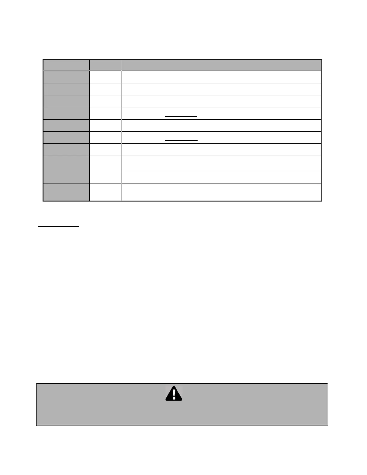
L.E.D
Color
Status
+24 V
Green When ON indicates the presence of 24VDC on the Logic Board
+5 V
Green When ON indicates the presence of 5VDC power in the Control Circuit
Open Limit
Red When ON indicates door position, completely open.
Open
Red
Only when the open relay
is activated (open relay is energized)
Close Limit
Red When ON indicates door position, completely close.
Close
Red
Only when the close relay is activated (close relay is energized)
Safe
Red Light ON only when safety devices are activated.
INDICATOR
Red
Flashes only when motor runs in opposite direction and activates the
wrong limit switch.
Stay ON only when the “centrifugal switch” is opened (please contact
technical support)
STOP
Yellow
In normal conditions light; stay ON, goes OFF every time when press
STOP button or hoist is engaged
WARNING
WHEN REPLACING AN ELECTRONIC CONTROL BOARD DO CHECK THAT ALL JUMPERS ARE
POSITIONED AS INDICATED IN THE WIRING DIAGRAMS ON PAGE 23 FOR SINGLE PHASE AND
ON PAGE 24 FOR 3-PHASE.
 Loading...