32
2
IT
EN
DE
MRT 1440-1640-1840
c1 - Beschreibung des
anzeigegeräts
Es gibt dem Fahrer Informationen, um im
sicheren Bereich zu arbeiten und gestattet die
Eingabe einsatzrelevanter Daten.
1 - Identifikationssymbole der Betriebsarten
der Maschine (stabilisiert, Frontalreifen,
400°/360° auf Reifen, teilweise stabilisiert).
Die Wahlvorgänge werden automatisch
vorgenommen.
2 - Identifikationssymbole der Geräte
(manuelle Wahl auf der Schalttafel mittels der
Taste A
).
3 - Grüne/Gelbe/Rote Leuchtanzeige, die den
Arbeitszustand angeben
(Sicherheit/Alarm/Sperre).
4 - Alphanumerische LCD-Display für die
Sichtanzeige der Arbeitsdaten.
5 - Symbole und Buchstaben zu den vom
Display gelieferten Anzeigen.
6 - Icon mit Reproduktion der Maschine und
den Buchstaben zu den angezeigten geome-
trischen Fahrzeugdaten.
7 - Taste zur Kontrastregelung.
8 - Taste zur Wahl der Geschwindigkeit der
hydraulischen Bewegungsabläufe: Standard
oder langsam.
9 - Taste zur Wahl des Zubehörtyps (unter
den vorhandenen).
10 - Taste zur Bestätigung des Zubehörteils
und des Kontrastwerts.
c1 - Descrizione del pannello di
controllo
Il pannello fornisce all’operatore tutte le
informazioni utili per lavorare
correttamente e permette le selezioni
necessarie.
1 - Simboli di identificazione dei modi
operativi della macchina (stabilizzata,
gomme frontali, 400°/360° su gomme,
stabilizzata parzialmente).
Le selezioni sono automatiche.
2 - Simboli di identificazione delle
attrezzature (selezione manuale sul
pannello attraverso il tasto
A
).
3 - Spie luminose Verde/Gialla/Rossa
indicanti la condizione di lavoro
(sicurezza/allarme/blocco).
4 - Display LCD Alfanumerico per la
visualizzazione dei dati di lavoro.
5 - Simboli e lettere relativi alle
indicazioni fornite dal display.
6 - Icona riproducente la macchina e le
lettere relative ai dati geometrici
visualizzati.
7 - Tasto di regolazione contrasto.
8 - Tasto per selezionare la velocità
dei movimenti idraulici: standard o
lenti.
9 - Tasto per selezionare il tipo di
accessorio (tra quelli presenti).
10 - Tasto per confermare l’accessorio e il
valore del contrasto.
1
2
3
4
5
6
7
c1
1
10
8
9
5
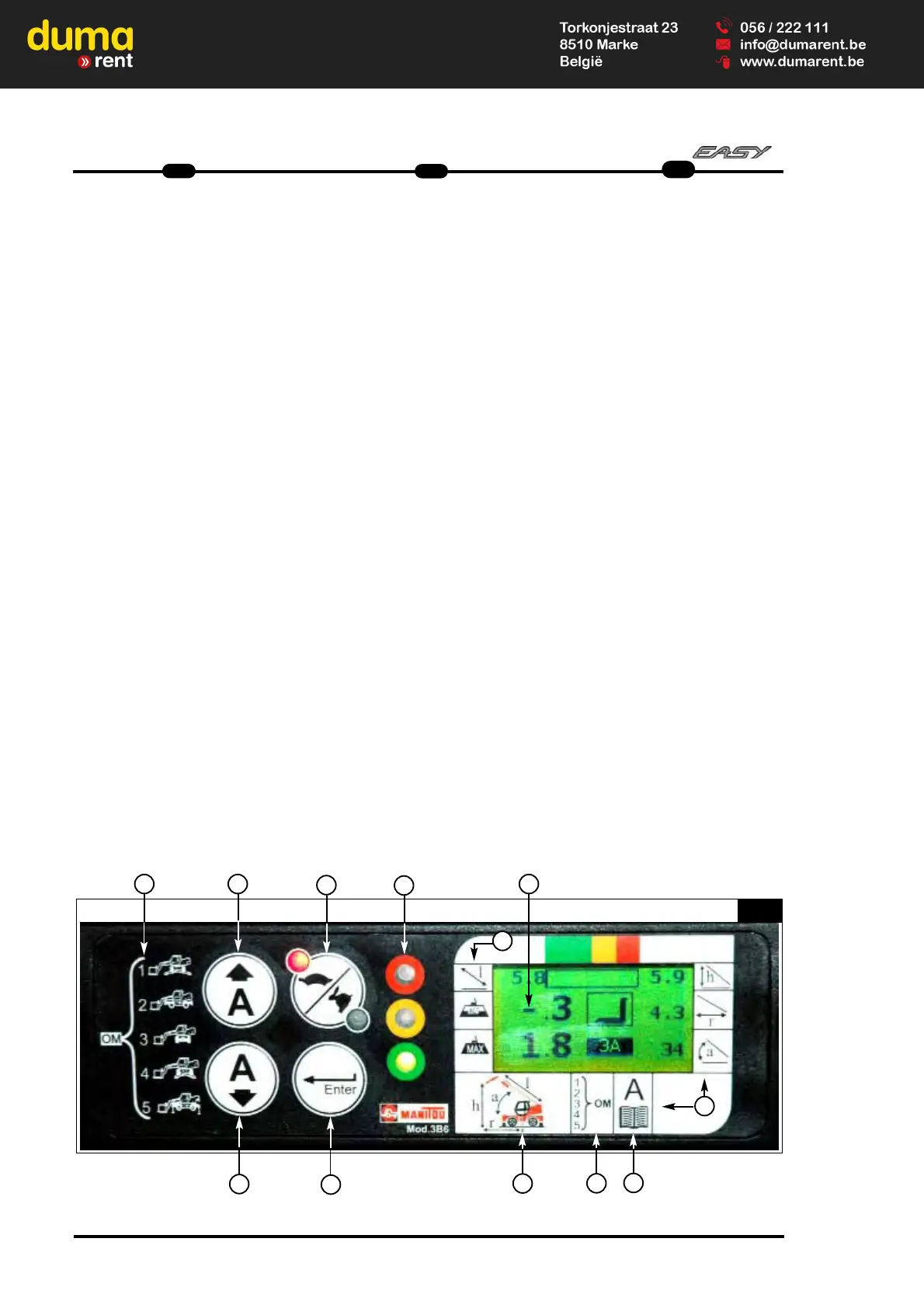
c1 - Control panel description
It gives to the operator all information in
order to work in safe conditions and
allows correct setting.
1 - Symbols identifying the operating
modes of the machine (stabilised,
frontal on tyres, 400°/360° on tyres,
partially stabilised).
The selections are made
automatically.
2 - Identification symbols of the
attachments (manual selection via the
panel using the
A
key).
3 - Green/Yellow/Red indicator lights
signalling the operating status
(safety/alarm/block).
4 - Alphanumerical LCD display showing
the operating data.
5 - Symbols and letters concerning the
indications provided by the display.
6 - Icon depicting the machine and the
letters of the geometric data
displayed.
7 - Contrast regulating key.
8 - Key for selecting the speed of the
hydraulic movements: standard or
slow.
9 - Key for selecting the type of
attachment (amongst those installed).
10 - Key for confirming the attachment
and contrast value.
 Loading...