Grove Published 3-25-2020, Control # 595-10 4-33
GRT8100 OPERATOR MANUAL SET-UP AND INSTALLATION
Making Electrical Connection Between Boom
Extension Base Section and Boom Nose
1. Remove bypass plug from boom nose splitter
connection and stow on cap near splitter connection.
2. Unwind cable from boom extension base section and
connect to boom nose splitter connection.
Making Electrical Connection Between Boom
Extension Base Section and Boom Extension Fly
Section
1. Disconnect cable from boom extension base section
anti-two block switch.
2. Connect boom extension base section cable to boom
extension fly section cable.
3. Install cap onto anti-two block switch on boom extension
base section.
Disconnecting
Disconnecting Electrical Connection Between Boom
Extension Base Section and Boom Nose
1. Disconnect boom extension base section cable from
boom nose splitter connection.
2. Install cap on cable and wind cable onto boom extension
base section for storage.
3. Remove bypass plug from cap near splitter connection
and install in splitter connection.
Disconnecting Electrical Connection Between Boom
Extension Base Section and Boom Extension Fly
Section
1. Remove cap from anti-two block switch on boom
extension base section.
2. Disconnect boom extension base section cable from
boom extension fly section cable.
3. Install cap onto plug of boom extension fly section cable.
4. Connect boom extension base section cable to anti-two
block on boom extension base section.
Disconnecting Hydraulic Connection Between Boom
Extension and Boom Base
1. Disconnect boom extension hoses from drum hoses. Do
not detach drum hoses from boom nose.
When working with main boom for longer periods of time,
hydraulic hoses should be disconnected from boom nose
and retracted. This prevents unnecessary reeling and
unreeling of the hose.
2. Remove hoses from boom nose. Retract hydraulic
hoses to holder on boom base.
3. Engage hose drum lock pin into hole on drum.
4. Wind hoses on boom extension base section for
storage.
5. Install dust caps on boom extension base section and
drum hose couplings.
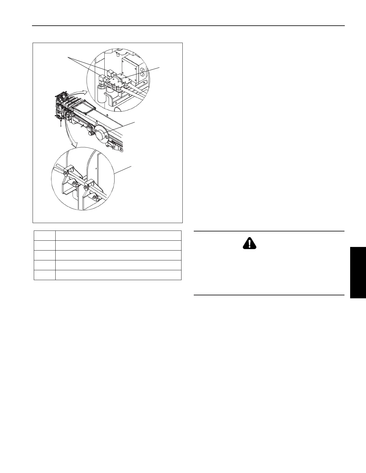
Item Description
1
Hydraulic Couplers
2 Holder
3 Guide Rollers
4 Hose Drum
WARNING
If hose couplings are detached from boom after hose
drum lock pin has been released, do not release hose
couplings until they are attached to the boom. If hose
couplings are released after being detached from the
boom, hoses will spring back uncontrollably due to spring
force in the hose drum.

 Loading...


