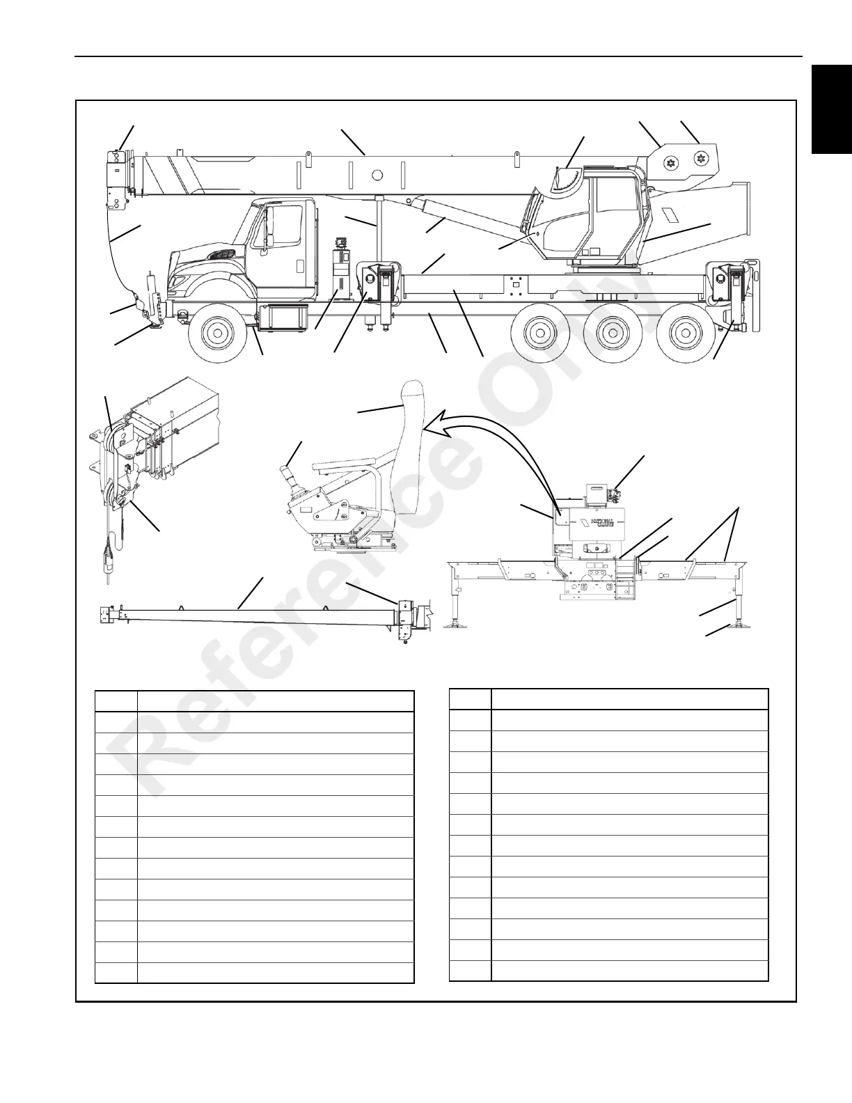
EasyManuals Logo

Manitowoc National Crane NBT40 Series Service Manual

Manitowoc National Crane NBT40 Series
220 pages
To Next Page IconTo Next Page
To Previous Page IconTo Previous Page
Page #13 background imageLoading...
Page #13 background image
National Crane Published 8-01-2017 Control # 287-11 1-3
NBT40 SERVICE MANUAL INTRODUCTION
1
10
FIGURE 1-2
Item Component
1 Crane Cab
2 Crane Cab console
3 Operator’s Seat
4Boom
5Boom Nose
6Boom Rest
7 Lift Cylinder
8 Downhaul Weight, Hook Block
9 Hoist (9a Auxiliary, 9b Main)
11 Outrigger Beam
12 Outrigger Jack
13 Out Rigger Float
14 Outrigger Box
15 Boom Angle Indicator
16 Hoist Cable
17 Jib
18 Turret
19 Stabilizer Front Outrigger (SFO), Front Outrigger Jack
20 Hydraulic Tank
21 Hydraulic Pump (not shown)
22 Hydraulic Remote Controller (HRC)
23 Truck Frame
24 Truck Bed
25 Torsion Box Frame, T-Box Frame
26 Sheave
Item Component
5
26
19
8
16
5
4
7
6
24
20
23
25
21
14
12
1
2
18
11
13
1
12
9
17
5
14
9a
9b
15
22
3
7474-1
7474-4
7474-2
7474-5
7474-3
Reference Only

Table of Contents

Other manuals for Manitowoc National Crane NBT40 Series

Questions and Answers:

Question and Answer IconNeed help?

Do you have a question about the Manitowoc National Crane NBT40 Series and is the answer not in the manual?

Manitowoc National Crane NBT40 Series Specifications

General IconGeneral
BrandManitowoc
ModelNational Crane NBT40 Series
CategoryConstruction Equipment
LanguageEnglish

Related product manuals