ELECTRIC SYSTEM NBT40 SERVICE MANUAL
3-6 Published 8-01-2017 Control # 287-11
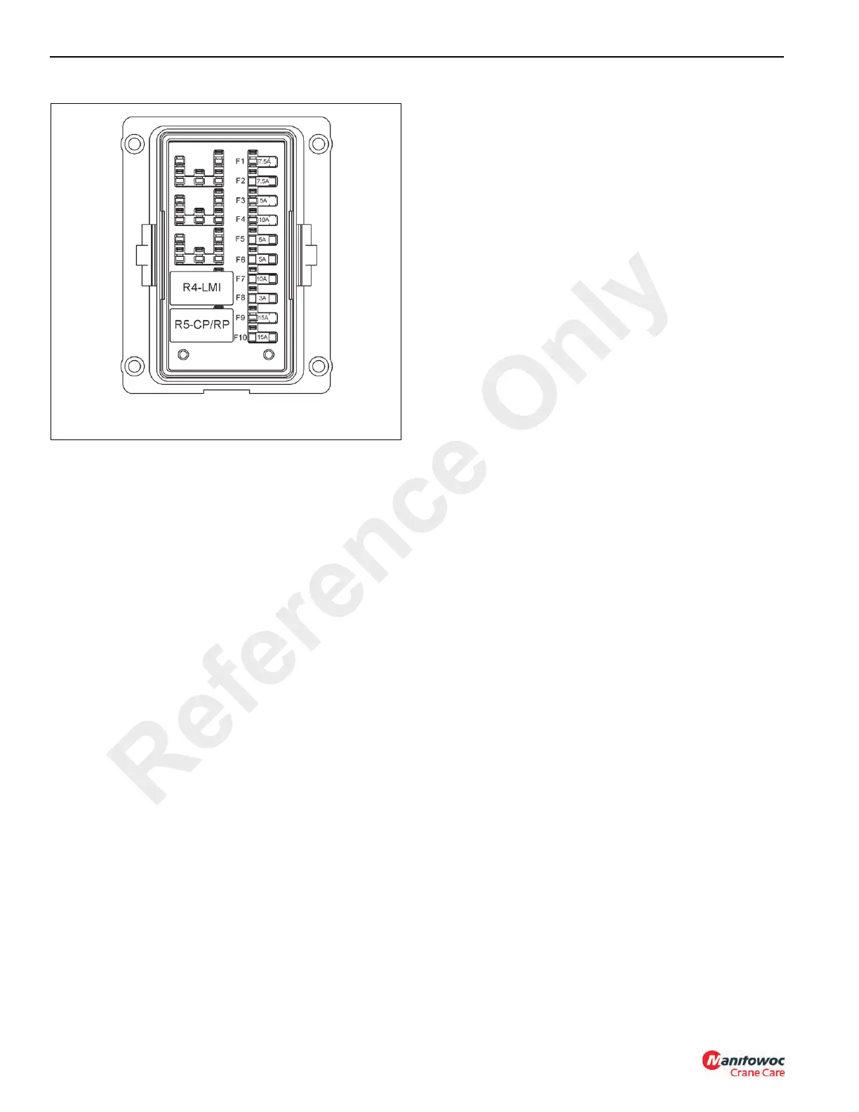
Fuse Box #3
Micro Relay Fuse Box #3
The micro relay fuse block (6, Figure 3-2) is located on the
right side of the fuse relay panel and contains the following
components, Figure 3-5:
• R1 - Not Used
• R2 - Not Used
• R3 - Not Used
• R4 - Rated Capacity Limiter (RCL) Relay
• R5 - Crane Power and Remote Power
• F1 - Spare - 7.5 amp
• F2 - Hoist Speed Switch - 7.5 amp
• F3 - Spare - 5 amp
• F4 - Spare - 10 amp
• F5 - MWI Lockout Solenoid - 5 amp
• F6 - Swing Brake Power, Hoist Thumper - 5 amp
• F7 - RCL Lockout Solenoid - 10 amp
• F8 - Hoist DRI/MWI Sensor - 3 amp
• F9 - Spare - 15 amp
• F10 - Outrigger Power - 15 amp
Reference Only
 Loading...


