BOOM MAINTENANCE NBT40 SERVICE MANUAL
4-2 Published 8-01-2017 Control # 287-11
Reference Figure 4-1, Figure 4-2, Figure 4-4 and Figure 4-5
for Boom Removal, Disassembly, Assembly and Cable
Tensioning.
Boom Removal
For Boom weight see Specifications in Section 9 of this
manual.
1. Extend and set machine outriggers and front stabilizer.
Boom must be completely retracted and stowed in boom
rest over front of truck.
2. If equipped, remove swing around jib according to
procedures outlined in the Set-Up Section of the
Operator’s Manual.
3. Remove hook block or downhaul weight, wind up rope
on hoist drum and stow wedge socket becket on pegs
provided on 1st section. Shut down truck engine.
4. Attach lifting device to the counterweight to provide even
weight distribution and raise the counterweight until
weight is removed from the boom pivot pin. Remove
counterweight retaining hardware from the boom pivot
pin and lower the counterweight until it rests on the rear
outrigger box.
5. Attach a lifting device to rod end of lift cylinder, remove
boom lift cylinder pin keeper and pin from bottom of 1st
section boom. Lower lift cylinder rod end to the deck.
6. Tag and disconnect extend cylinder lines and hoist
hydraulic and electric lines. Cap all openings. Unplug
anti-two-block/RCL cord from receptacle in turret.
7. Disconnect and cap all hoist hydraulic lines and
openings. Hoist may be removed at this point, but is not
necessary. (See “Hoist Removal” on page 5-2).
8. Attach a lifting device to provide even weight distribution
and raise the boom until weight is removed from the
boom pivot pin. Remove boom pivot pin keeper and
boom pivot pin. Lift boom free of turret.
Additional Maintenance, Disassembled
Boom
1. Clean all boom sections and inspect for wear, dents,
bent or crooked boom sections, gouged metal, broken
welds or any abnormal conditions. Repair or replace as
required.
2. Inspect all sheaves for excessive groove wear or
abnormal rim wear. Replace as required.
3. Inspect all sheave bearings for excessive wear or cut
inner liner material. If installed bearing diameter is
0.015 in larger than pin diameter, bearing must be
replaced. Any cut or gouge which causes the bearing
liner to lose strands is cause for bearing replacement.
4. Clean and inspect all cable assemblies according to wire
rope inspection procedures in this section. Pay
particular attention to any wire breakage at the end
connections. Replace cable assemblies as required.
Lubricate all cable assemblies before reinstalling them
in boom.
5. Inspect all sheave pins for nicks, gouges or pitting due to
rust in the bearing surface area. Replace if any damage
is evident.
6. Inspect all grease fittings and grease paths in pins to
ensure proper grease flow. Clean and replace as
required.
7. Replace all lubricating plugs (36) in all wear pads as
necessary.
Four Section Cable Tensioning
After Boom Assembly or if Interior proportioning cables
appear loose, cable tensioning may be required.
Tensioning Setup Procedure
Tensioning must be done with the boom in the horizontal
position. reference Figure 4-4
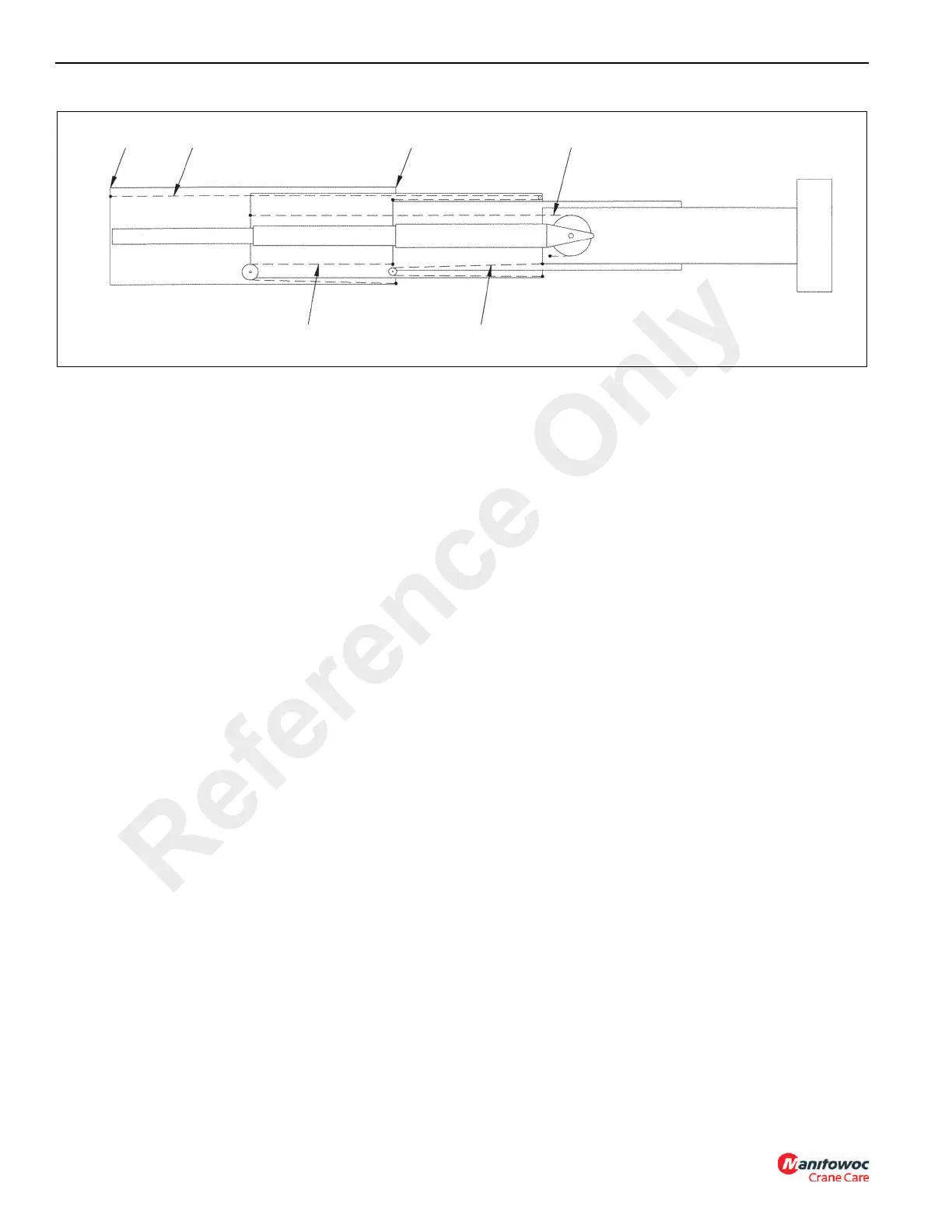
BASE 1/2/3 EXTEND TIP 2/3/4 EXTEND
1ST STAGE 2ND STAGE 3RD STAGE 4TH STAGE
3/2/1 RETRACT
4/3/2 RETRACT
FIGURE 4-1
Reference Only

 Loading...


