National Crane Published 8-01-2017 Control # 287-11 9-31
NBT40 SERVICE MANUAL CRANE INSTALLATION
Counterweight Installation
1. Position the crane on a firm level surface. Fully extend
and set the outriggers
2. Position the superstructure over the front of the machine
and engage the turntable lock.
3. Install two lifting bolts into the 1.25 x 7 UNC lift inserts (2,
Figure 9-19). Using a proper lifting device attach straps
to each bolt, lift and place the counterweight inside the
crane support weldment.
4. With the lifting device still attached, align the two
counterweight and crane support weldment holes and
install two bolts (1, Figure 9-20), lockwashers (2), nuts
(3).
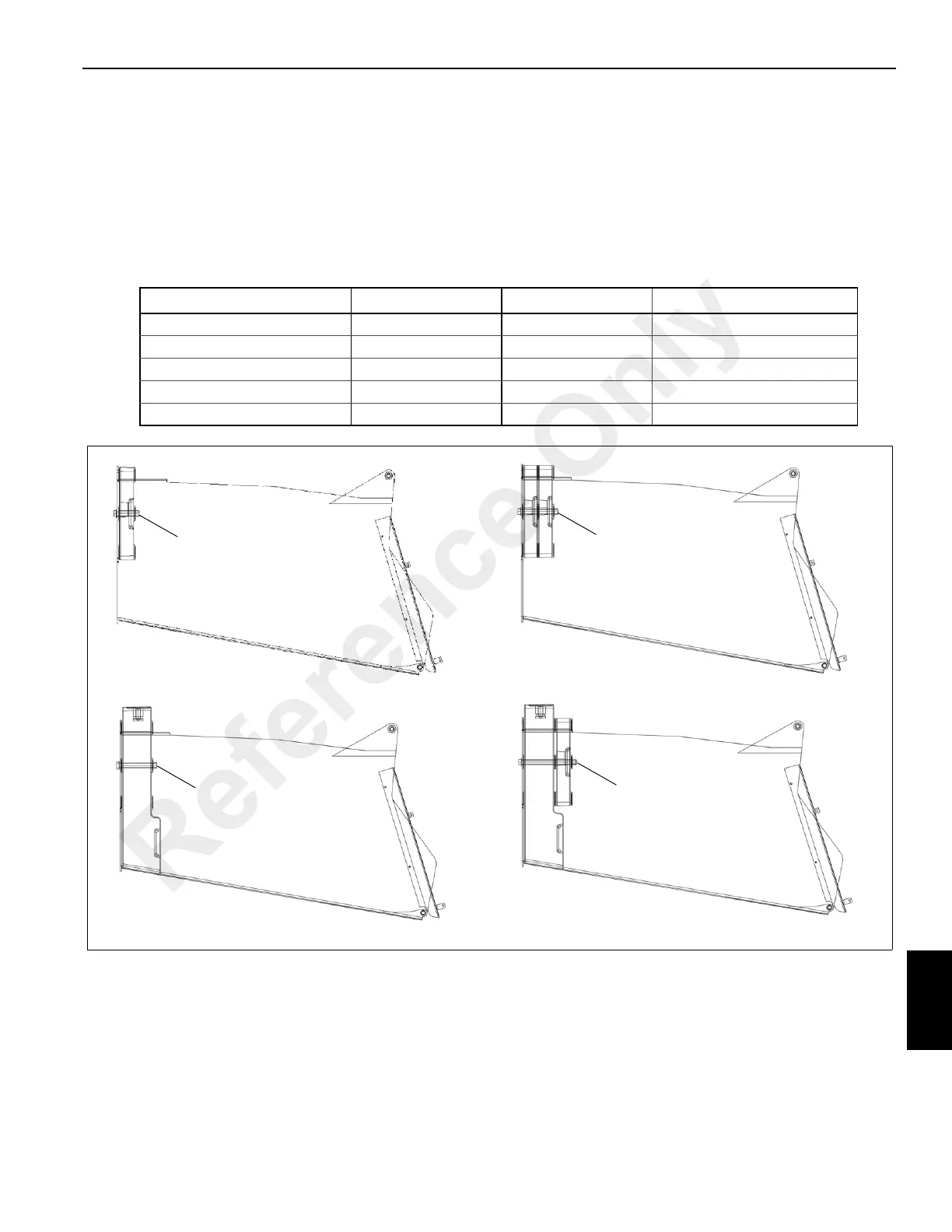
Counterweight Table
Model Plate Part Number Description Figure 9-20 Letter Call Out
NBT36 N/A N/A N/A
NBT40 Standard 80018805 1000 lbs A
NBT40 + 1000 Option 80018805 (2) 2000 lbs B
NBT45 Standard 80018804 4500 lbs C
NBT45 + 1000 Option 80020222 5500 lbs D
A
B
C
FIGURE 9-20
1,2,3
1,2,3
1,2,3
1,2,3
D
Reference Only
 Loading...


