EasyManuals Logo

Manitowoc National Crane NBT40 Series Service Manual

Manitowoc National Crane NBT40 Series
220 pages
To Next Page IconTo Next Page
To Previous Page IconTo Previous Page
Page #198 background imageLoading...
Page #198 background image
CRANE INSTALLATION NBT40 SERVICE MANUAL
9-20 Published 8-01-2017 Control # 287-11
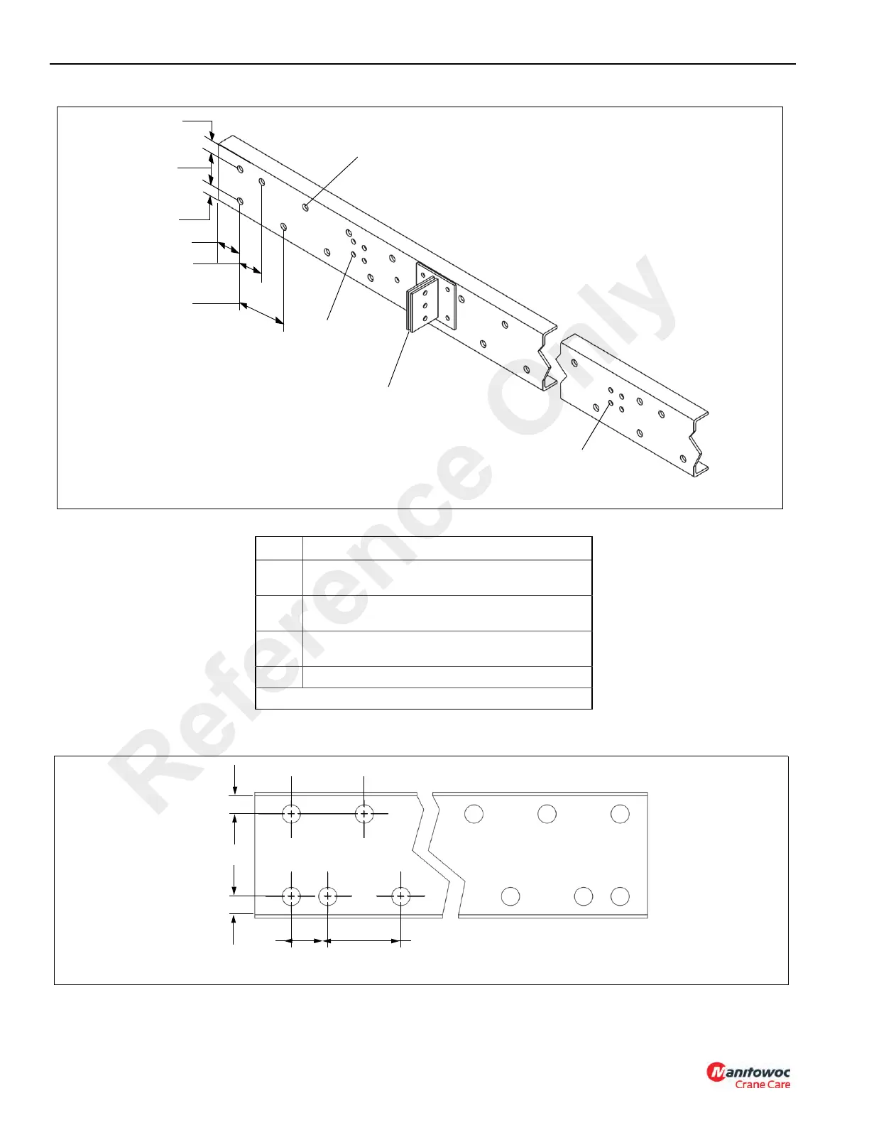
Figure 9-12 Item Numbers
Item Description
1
Crossmember bolt holes. Shift the plug weld holes
slightly to clear the crossmember holes.
2
Planned location of mounting plate. Plug weld locations
can be shifted to clear plate.
3
Clearance holes for rivets on weld or on reinforcement.
Can be filet welded around to eliminate plug weld holes.
4 1" (25.4) diameter holes for plug welds
NOTE: All Figure 9-12 dimensions are inches
1
4
4
8
2
5
2
4
3
2
FIGURE 9-12
8" Typ
4"
2" Min
2" Min
FIGURE 9-13
Reference Only

Table of Contents

Other manuals for Manitowoc National Crane NBT40 Series

Questions and Answers:

Question and Answer IconNeed help?

Do you have a question about the Manitowoc National Crane NBT40 Series and is the answer not in the manual?

Manitowoc National Crane NBT40 Series Specifications

General IconGeneral
BrandManitowoc
ModelNational Crane NBT40 Series
CategoryConstruction Equipment
LanguageEnglish

Related product manuals