EasyManuals Logo

Manitowoc National Crane NBT40 Series Service Manual

Manitowoc National Crane NBT40 Series
220 pages
To Next Page IconTo Next Page
To Previous Page IconTo Previous Page
Page #44 background imageLoading...
Page #44 background image
HYDRAULIC SYSTEM NBT40 SERVICE MANUAL
2-8 Published 8-01-2017 Control # 287-11
Hydraulic Valve Locations
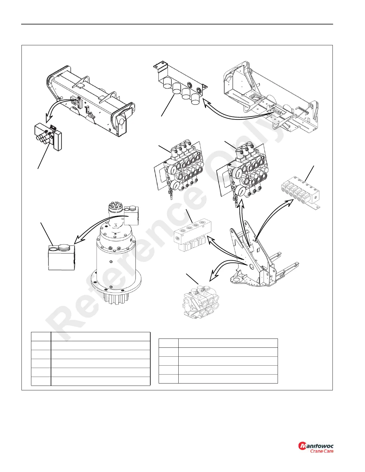
5 Rear Outrigger Solenoid Manifold
6 Front Outrigger Solenoid Manifold
7 Outrigger Pressure Reducing Valve
8 Swing Speed Control Valve
Item Component
5
FIGURE 2-1
4
1a
3
2
5
6
8
Item Component
1a Main Control Valve (lift, telescope, hoist)
1b Main Control Valve (Optional Aux Hoist)
2 Swing Control Valve
3 Pilot Valve (Air Conditioner/Swing Brake)
4 Dump Valve
1b
Reference Only

Table of Contents

Other manuals for Manitowoc National Crane NBT40 Series

Questions and Answers:

Question and Answer IconNeed help?

Do you have a question about the Manitowoc National Crane NBT40 Series and is the answer not in the manual?

Manitowoc National Crane NBT40 Series Specifications

General IconGeneral
BrandManitowoc
ModelNational Crane NBT40 Series
CategoryConstruction Equipment
LanguageEnglish

Related product manuals