NBT40 SERVICE MANUAL HYDRAULIC SYSTEM
National Crane Published 8-01-2017 Control # 287-11 2-11
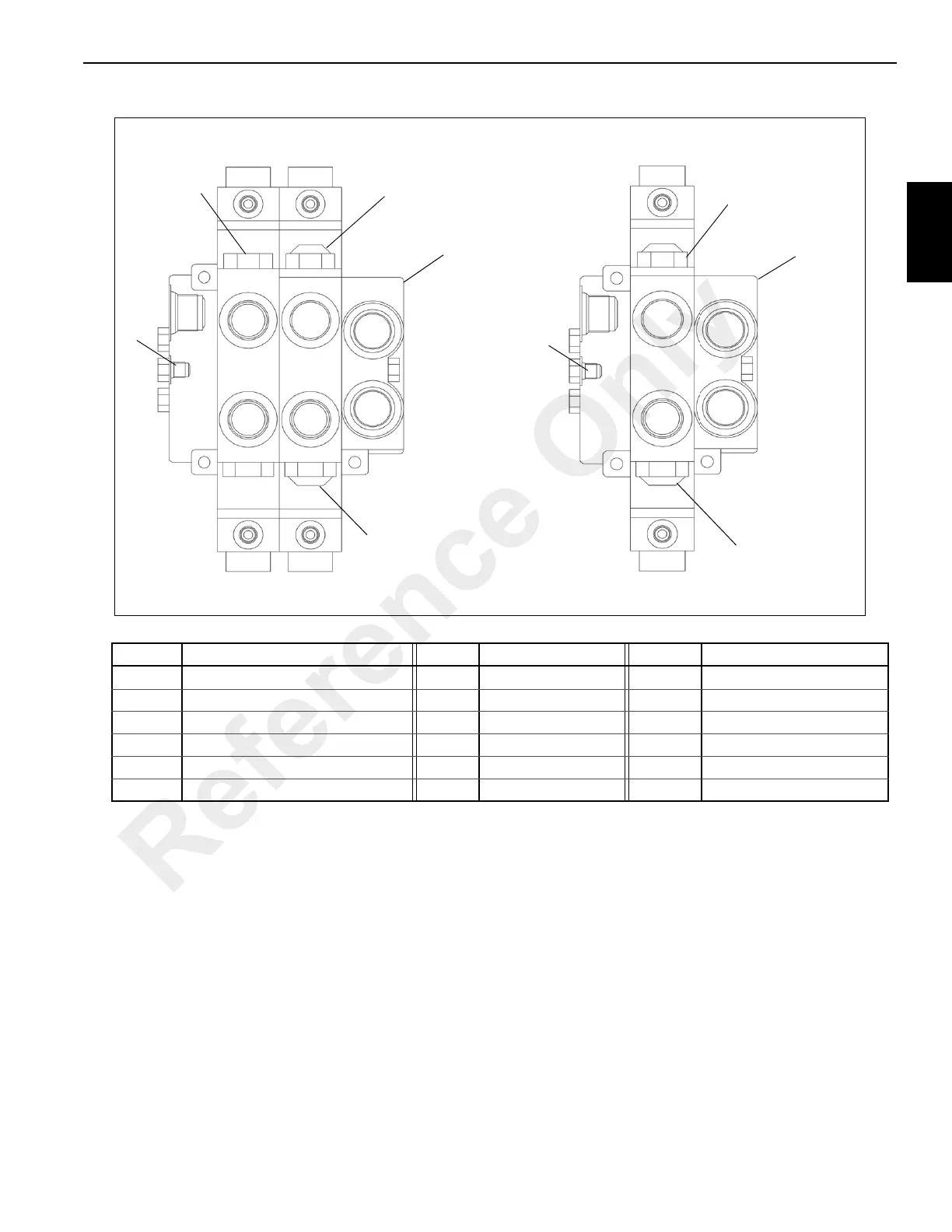
Swing Control Valve
Swing Control Valve Item List & Port/Hosing
Item/Port Description Item/Port Description Item/Port Description
A Swing Control Valve w/Aux Hoist & A/C J4 N Hose - A/C Pressure
B Swing Control Valve w/out A/C J5 P Hose - Swing Motor
1 Swing Relief Valve - Swing Motor X3 Hose - Pilot Manifold A2 R Outlet - Swivel 4A
2 Swing Relief Valve - Swing Motor X4 Hose - Pilot Manifold P T Inlet - Swivel 3A
3 Load Sense Port - Swing Motor L Hose - A/C Return
4 A/C Relief Valve M Hose - Swing Motor
T
P
R
L
M
N
R
T
M
P
2
1
A
1
4
3
X3
J4
J5
X4
B
2
3
J4
J5
75881-1
75881-2
FIGURE 2-4
Reference Only
 Loading...


