RATED CAPACITY LIMITER NBT50 OPERATOR MANUAL
7-8 Published 03-23-2018 Control # 243-14
of Screen 6. The non-current span setting will be shown in
gray.
The position of each outrigger will be shown graphically on
the right of the screen and will be either Full-Span, Mid-Span,
Zero-Span, Figure 7-4.
The shortest outrigger position determines the chart that is to
be used. For example:
In Figure 7-5 one side of the outriggers is at full-span and the
other side is at mid-span. In the Figure 7-5 example, the
configuration selected by the RCL and shaded in blue on the
left of the display screen would be Mid-span.
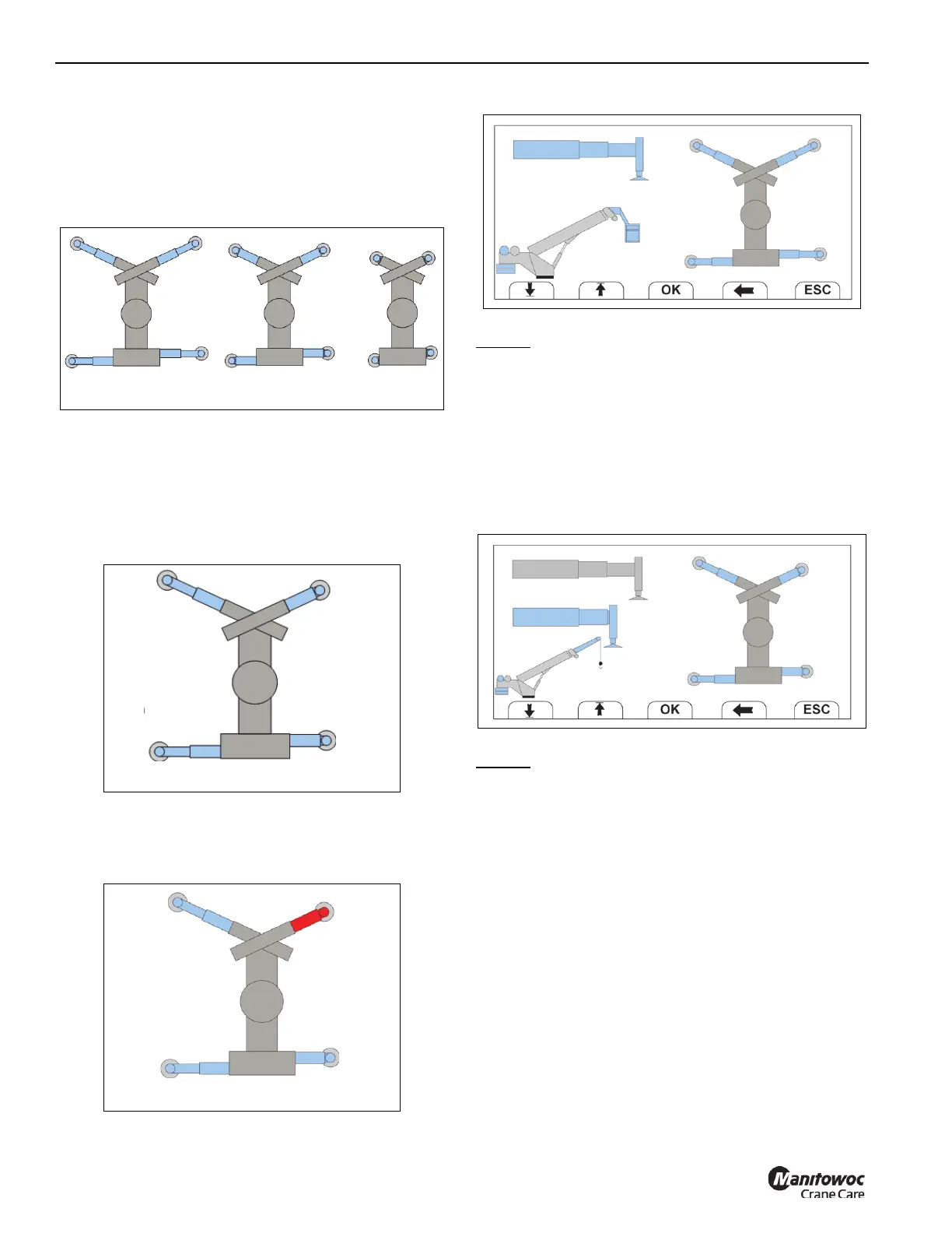
If any of the four Outrigger Length Monitoring Sensors are
out of range or not functioning properly, that beam will show
at midspan position and will be colored in red (Figure 7-6).
Screen 6-1
When using the personnel basket, Full-Span outriggers are
required
. Select OK after machine is in Full-Span.
If user attempts to select OK before Full-Span condition is
met, the OK button will color RED when depressed and the
the user can override the setup using the arrow keys.
If the user selects a setup configuration different than the one
selected by the RCL, the O/R override icon will be displayed
on screen 9 and on the RCL Operating Mode Screen shown
on page 7-9.
Screen 6-2
When using the jib, Full-Span or Mid Span outrigger’s are
required
. Select OK after machine is in Full or Mid-Span.
If user attempts to select OK before Full-Span or Mid-Span
condition is met, the OK button will color RED when
depressed and the user can override the setup using the
arrow keys.
If the user selects a setup configuration different than the one
selected by the RCL, the O/R override icon will be displayed
on Confirmation Screen (screen 9 on page 7-9) and on the
RCL Operating Screen shown on page 7-9.
FIGURE 7-4
7521-10b
All O/R’s@Full-Span
All O/R’s@Mid-Span
All O/R’s@Zero -Span
FIGURE 7-6
7521-10c
Error with
one sensor
 Loading...


